
Systems and methods for printing by using a position-coding pattern

a position-coding pattern and printing system technology, applied in printing, typewriters, electrical devices, etc., can solve the problems of printers not being able to print subsequent images at the correct position, printers tend to be relatively bulky, inconvenient to carry, etc., and achieve the effect of resuming printing upon interruption

Inactive Publication Date: 2005-02-15
ANOTO AB
View PDF39 Cites 118 Cited by
  • Summary
  • Abstract
  • Description
  • Claims
  • Application Information

AI Technical Summary

Benefits of technology

"The present invention relates to printing graphical information on a surface. The invention can print on surfaces with arbitrary shapes without detecting the edges of the surface during printing. Additionally, the invention can easily resume printing upon interruption. The system includes a nozzle for dispensing dye on the surface and an image sensor for recording an image of the surface. The nozzle can dispense dye on the surface by comparing the recorded image with the graphical information to be printed. The system can also print indicia on the surface based on a comparison of the recorded image and a coordinate position defined by a position-coding pattern on the surface. The method includes recording an image of the surface and then printing indicia on the surface based on a comparison of the recorded image and the graphic information. The technical effects of the invention include the ability to print on surfaces with arbitrary shapes and the ability to easily resume printing upon interruption."

Problems solved by technology

In their current forms, both inkjet and laser printers tend to be relatively bulky and inconvenient to carry, making them ideal for portable use such as with a portable computer.
Thus, if the user lifts the printer during printing, the printer may not be able to print subsequent images at the correct position

Method used


Image

  • Systems and methods for printing by using a position-coding pattern
  • Systems and methods for printing by using a position-coding pattern
  • Systems and methods for printing by using a position-coding pattern

Examples


Embodiment Construction

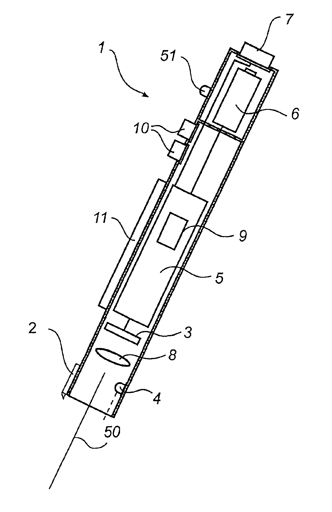
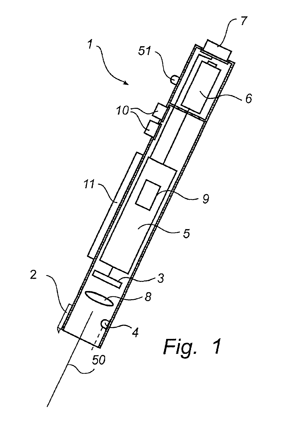
Systems and methods consistent with the present invention will now be described with reference to the accompanying drawings. FIG. 1 shows a printer 1 consistent with a preferred embodiment of the present invention. As shown in FIG. 1, the printer 1 preferably comprises an inkjet head 2, an image sensor 3 for recording an image of the surface, and a diode 4 for illuminating the surface. The inkjet head 2 may include a nozzle for dispensing ink on a surface. Further, in order for the position of images recorded by the image sensor 3 to correspond with the position of the nozzle, the inkjet head 2 may be located adjacent to the image sensor 3 at one end of the printer. In front of the image sensor 3, which may comprise a charge coupled device (CCD), there may be located a lens system 8 for imaging the coding pattern on the CCD.

The printer 1 may also comprises an image-processing means 5 for processing an image recorded by the image sensor 3, a power supply 6 (e.g., a battery) for suppl...


PUM


Abstract

Systems and methods consistent with the present invention include a printer for printing graphical information on a surface. The printer includes a print head for printing indicia on the surface and an image sensor for recording an image of the surface. The recorded image contains a position-coding pattern that identifies a position on the surface. A processor converts the recorded image into a recorded position, and the print head then prints indicia on the surface based on a comparison of the recorded position with the graphical information to be printed.

Description

BACKGROUND OF THE INVENTION1. Field of the InventionThe present invention relates to systems and methods for printing, and, more particularly to a printing device using a position-coding pattern.2. Description of the Related ArtPortable computers are becoming increasingly popular in our society. While such computers can process information and display the results on a display screen, they must be connected to a portable printer to print the results on paper. Generally, computers are connected to a network printer via a network connection.Currently, network printers can be generally separated into two categories: laser printers and inkjet printers. Laser printers operate by charging parts of a sheet of paper with static electricity. When toner is applied, it will adhere to the parts of the sheet charged by the static electricity. A heating process is then used to make the toner stick to the sheet. Inkjet printers, on the other hand, operate by passing an inkjet head over the surface ...

Claims


Application Information

Patent Timeline
Patent Type & Authority Patents(United States)
IPC IPC(8): B41J2/045H04N1/047H04N1/107
CPCH04N1/047H04N1/107H04N2201/0471H04N2201/04717H04N2201/04734H04N2201/04743
Inventor ERICSON, PETTERBURSTROM, STEFAN
Owner ANOTO AB
Learn More