
Internal combustion engines and control

a technology of internal combustion engine and control, which is applied in the direction of automatic control of ignition, machines/engines, liquid fuel feeders, etc., can solve the problems of long preparation time of fuel to create carburated charge, direct injection engines generally attempt to generate non-uniform distribution of fuel within combustion chambers, and stratified air and fuel charge, etc., to achieve low cost

Inactive Publication Date: 2005-02-15
ORBITAL ENGINE CO PTY LTD
View PDF32 Cites 15 Cited by
  • Summary
  • Abstract
  • Description
  • Claims
  • Application Information

AI Technical Summary

Benefits of technology

"The present invention provides an internal combustion engine with a low tumble inlet port and a valved inlet duct that creates a low tumble gas motion in the combustion chamber, which reduces over-enrichment of fuel in the end gas regions. This reduces emissions and improves combustion stability. The engine also utilizes a spray-guided, central injection fuel delivery system of air-assisted type, which allows for a comparatively retarded ignition time window and potentially reduced emissions levels. The invention is particularly useful in strated charge engines with spray-guided, central direct injection fuel delivery systems."

Problems solved by technology

The result of both charge guided and wall guided transportation methods is a longer preparation time of the fuel to create the carburated charge.
Modern gasoline direct injection engines generally attempt to generate a non-uniform distribution of fuel within the combustion chamber.
This non-uniform distribution is commonly referred to as a stratified charge and means that typically one-region of the combustion chamber has a greater concentration of fuel than the remainder of the combustion chamber during certain load conditions.
By injecting later in the cycle, the fuel spray has a limited amount of time to mix with the intake air in the combustion chamber, resulting in a stratified charge of air and fuel.
However, two of the major problems associated with single fluid implementation of spray guided combustion systems are spark plug durability and steep air / fuel ratio gradients which lead to poor robustness of combustion.
However, even with AADI spray guided systems it has been found that the levels of emissions present in the engine out gasses indicate that spray guided systems can still generate imperfect and / or partial combustion of hydrocarbons present in the fuel.
Thus operating a spray guided direct injection fuel system in a stratified manner has the potential to further degrade the engine out emissions generally expected.

Method used


Image

  • Internal combustion engines and control
  • Internal combustion engines and control
  • Internal combustion engines and control

Examples


Embodiment Construction

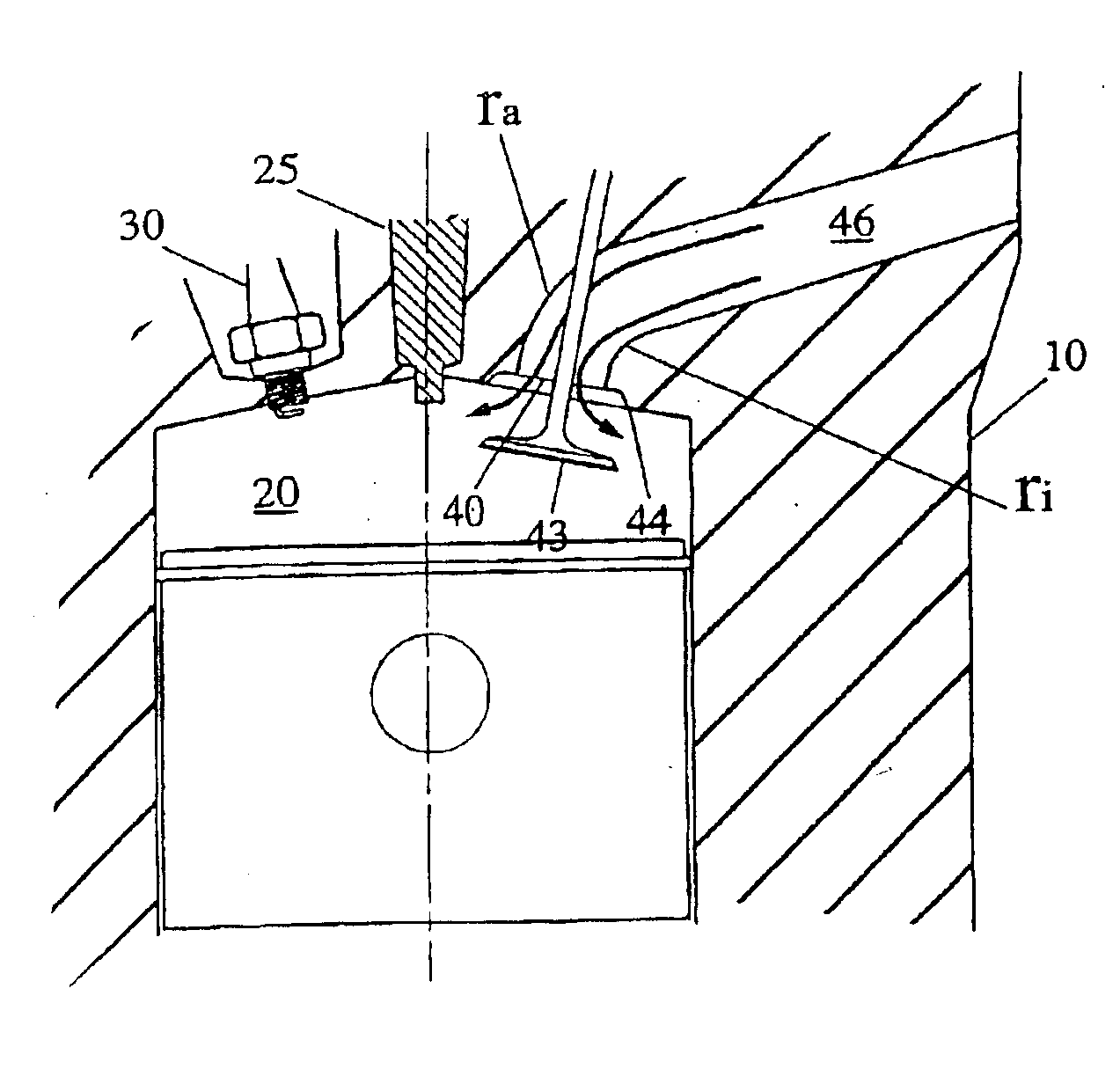
The present invention has identified that maintaining specified intake port flow characteristics positively Influence the combustion process where central direct fuel injection systems and particularly spray guided systems are employed in four stroke, spark ignited engines. A description of an experimental engine that embodies and confirms the potential advantages provided by the combination of low tumble inlet port engines and central spray guided fuel injection systems in accordance with the present invention will be given below.

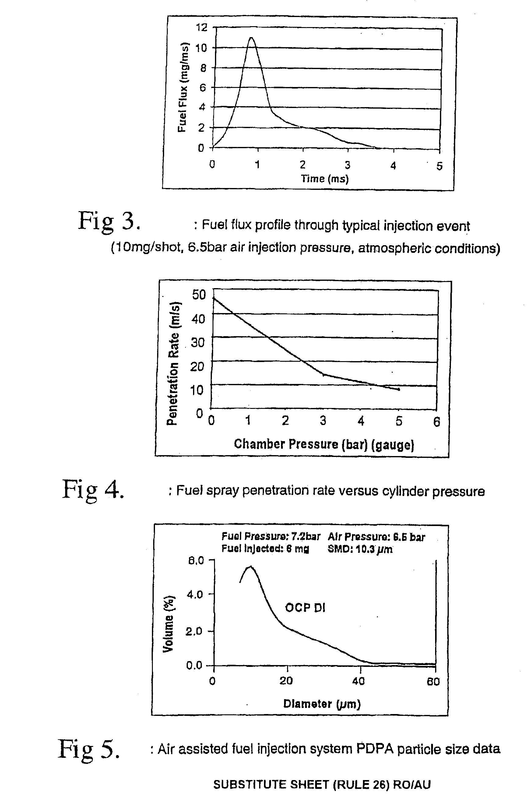
Direct in-cylinder spray guided Injection systems may utilise air-assisted direct injection fuel systems to achieve good combustion of Injected fuel. Air-assisted direct injection fuel systems have many facets, which are unique in comparison to present single fluid direct injection systems based on delivery of fuel at high pressure. Perhaps the most obvious difference is the addition of a second fluid (normally air), apart from fuel, which is injected dire...


PUM


Abstract

Disclosed is an internal combustion engine comprising at least one cylinder with a reciprocating piston to provide said engine with at least one combustion chamber, said combustion chamber further comprising a delivery injector for injecting fuel directly into said combustion chamber, said engine further comprising at least one valved inlet air duct for delivering combustion air into said combustion chamber, wherein at least said inlet air duct and / or its valve is arranged to provide a low tumble inlet port to said at least one combustion chamber, said combustion chamber, in use, having low in-cylinder tumble gas motion of said combustion air and wherein said low in-cylinder tumble gas motion of said combustion air reduces over-enleanment of fuel in end gas regions of said combustion chamber.

Description

FIELD OF THE INVENTIONThis invention is directed to spark-ignited internal combustion engines utilising direct in-cylinder (DI) fuel injection systems, in particular spray guided 5 systems and dual fluid injection systems, often referred to as air assisted injection (AADI) systems, and to the control of such internal combustion engines and particularly to four stroke engines utilising AADI gasoline fuel injection systems.BACKGROUND TO THE INVENTIONDirect injection gasoline engine technology is becoming increasingly popular due to the potential to reduce fuel consumption with little compromise to what the automotive gasoline engine offers today in terms of power density and cost. In order to provide a better understanding of the invention described below, some background as to different types of fuel injection and combustion systems is appropriate.Direct injected (DI) engines operate with fuel being directly Injected into the engine cylinders (ie combustion chambers), as compared to ...

Claims


Application Information

Patent Timeline
Patent Type & Authority Patents(United States)
IPC IPC(8): F02B17/00F02F1/42F02B23/10F02B75/12F02F1/24F02B75/00F02P5/15F02B31/00F02M61/14F02M67/02F02M67/12F02M69/08
CPCF02B17/005F02B23/101F02F1/4214F02B2023/106F02B2075/125Y02T10/123F02F2001/245Y02T10/125Y02T10/146Y02T10/12F02F1/42
Inventor CATHCART, GEOFFREY PAULZAVIER, CHRISTIAN CHANDRAKUMARRAILTON, DONALD ANDREWMCGRATH, JOHN ROY
Owner ORBITAL ENGINE CO PTY LTD
Learn More