
Pneumatic tool lock

a tool lock and pneumatic technology, applied in the field of pneumatic tool locks, can solve the problems of not all tools can be secured in such a fashion, tools remain unsecured, and tools can be fairly expensive to replace and may be dangerous

Inactive Publication Date: 2005-02-15
MASTER LOCK COMANY LLC
View PDF22 Cites 37 Cited by
  • Summary
  • Abstract
  • Description
  • Claims
  • Application Information

AI Technical Summary

Benefits of technology

A lock for securing a pneumatic tool from unauthorized use or theft is provided. In one embodiment, the lock includes a lock housing with a cylinder assembly disposed therein. The lock also includes an inner surface that retains a set of spring-loaded locking balls. The locking balls engage a groove in a pneumatic fitting once inserted into the lock housing. The lock further includes a set of raised surfaces that engage the locking balls when in the locked position and thereby prevent the locking balls from withdrawal from engagement with the pneumatic fitting.

Problems solved by technology

These tools can be fairly expensive to replace and may be dangerous, especially if used by an unauthorized person, such as a child.
However, not all tools can be secured in such fashion.
In particular, some tools are left out in the open for anyone to take or use simply because a locking mechanism has not been provided.
In other circumstances, tools remained unsecured because the locking mechanism provided cannot be adapted to secure the specific tool.

Method used


Image

  • Pneumatic tool lock
  • Pneumatic tool lock
  • Pneumatic tool lock

Examples


Embodiment Construction

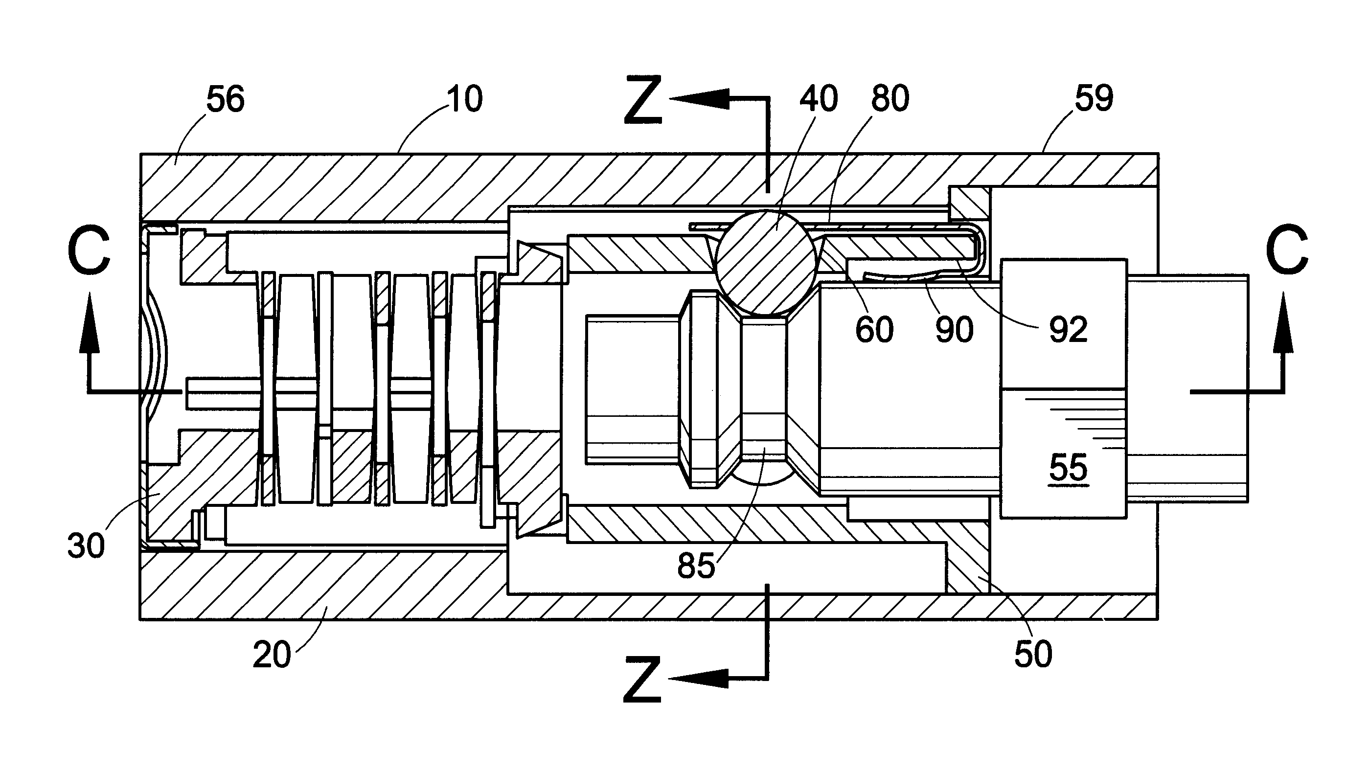
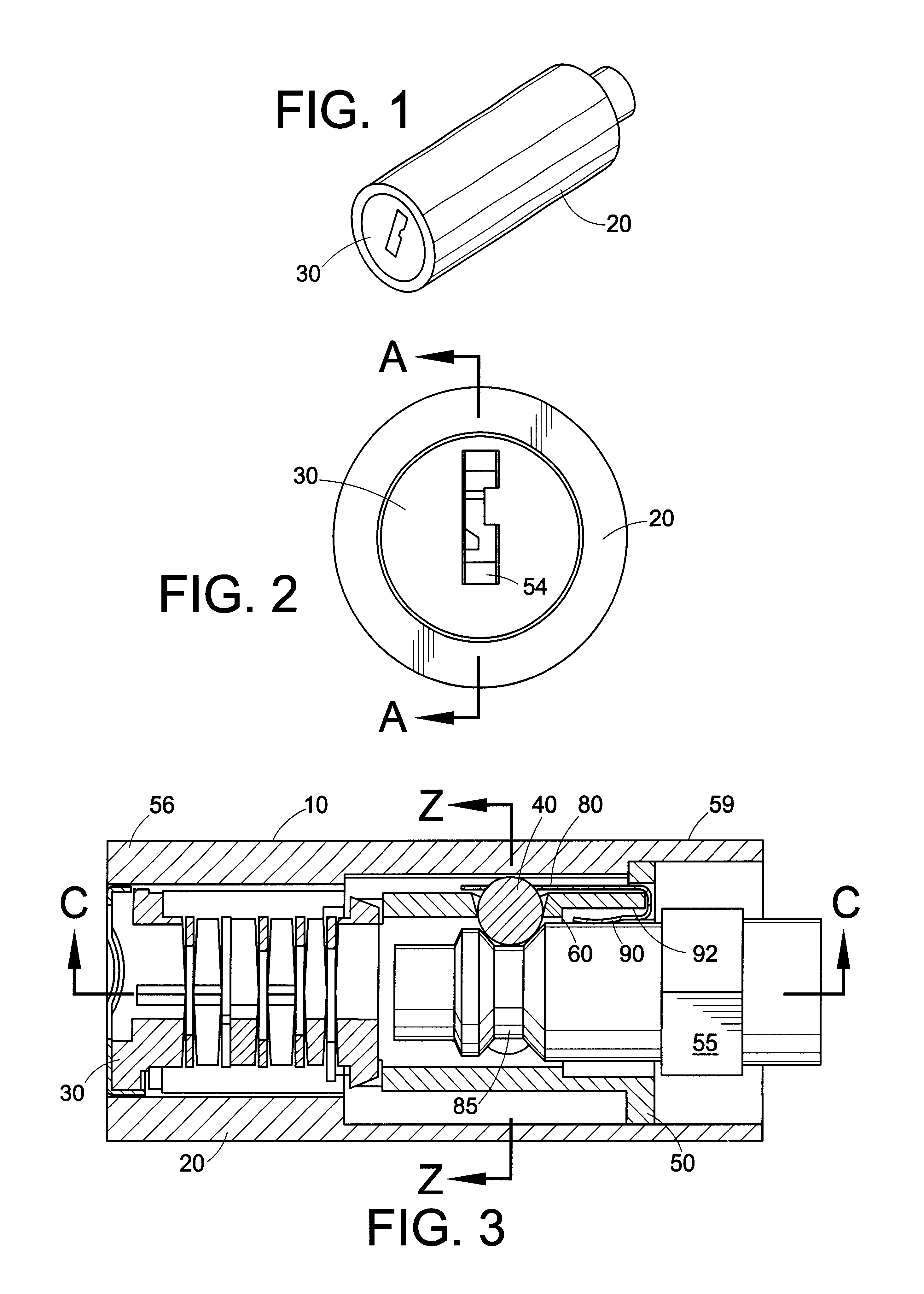
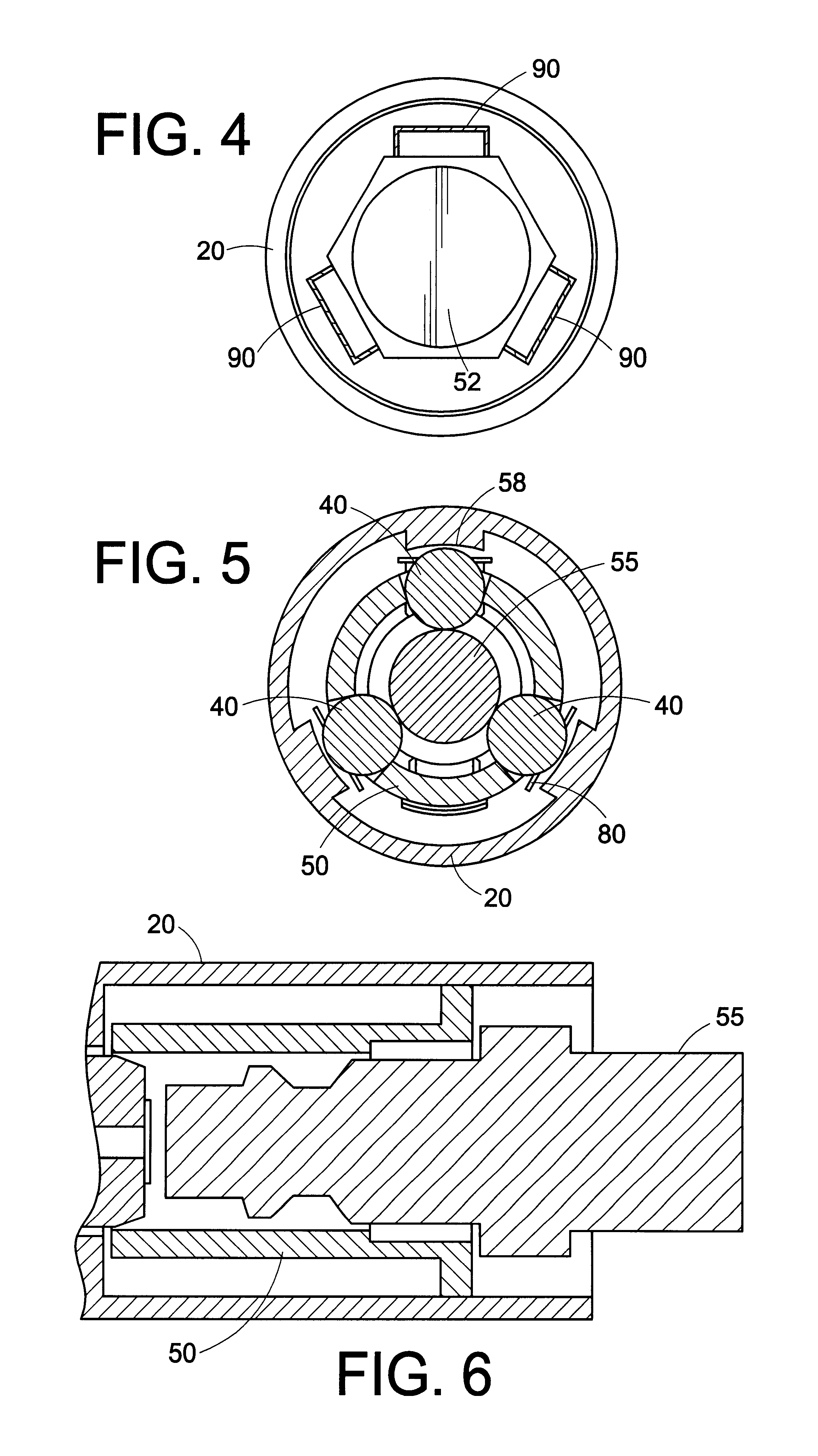
The present invention is a lock for securing pneumatic tools, generally referenced as 10. The lock includes lock housing 20, cylinder assembly 30, and one or more spring-loaded locking balls 40 located within a locking cavity of the lock housing, three are shown in the embodiment shown in FIG. 5. The lock housing 20, generally is cylindrical with an inner housing 50 located therein. In should be appreciated that the lock body may be various shapes, sizes and configuration providing that it provides the same functional aspects as described herein. The lock housing 20 is generally a hardened metal that provides security for the internal components of the lock 10. The lock housing may be provided wit an external coating of material, such as, for example, rubber or plastic if an external metal surface is not desired. Such an external coating can prevent the lock from scratching other surfaces, such as the surface of the tool to which the look is applied. The cylinder assembly 30 is hous...


PUM


Abstract

A tool lock, especially useful in preventing theft or unauthorized use of a tool. The tool lock has a housing in which a lock cylinder assembly and locking balls are disposed. The tool lock housing has an opening at one end in which a portion of a tool, such as a pneumatic fitting on a pneumatic tool, may be inserted and secured by the engagement of the locking balls. The tool lock housing may further include a shackle portion which can be used in conjunction with a cable, either integral or separate, padlock, or chain to secure the tool lock to another object.

Description

FIELD OF THE INVENTIONThe invention relates to a lock for tools, and more specifically to a tool lock that engages a pneumatic fitting on a pneumatic tool thereby securing the tool from theft and / or unauthorized use.BACKGROUND OF THE INVENTIONPneumatic tools, such as, for example, nail guns, staple guns, impact wrenches, and body grinders are commonly found on contractor sites, in assembly plants, in automotive repair workshops, and in some homes. These tools can be fairly expensive to replace and may be dangerous, especially if used by an unauthorized person, such as a child.Currently, pneumatic tools are protected from theft or unauthorized use by locking them in safe boxes with a padlock, or using a specially manufactured lock that prevents use of the tool. However, not all tools can be secured in such fashion. In particular, some tools are left out in the open for anyone to take or use simply because a locking mechanism has not been provided. In other circumstances, tools remain...

Claims


Application Information

Patent Timeline
IPC IPC(8): E05B67/36E05B67/00E05B73/00
CPCE05B67/365E05B73/0005Y10T70/443Y10T70/5009Y10T70/5022Y10T70/5628Y10T70/5867Y10T70/7751Y10T137/7069
Inventor ZAPUSHEK, JOHNIRGENS, CHRISTOPHER R.
Owner MASTER LOCK COMANY LLC
Learn More