Computer controlled engine adjustment based on an exhaust flow

a computer controlled engine and flow technology, applied in the direction of electrical control, process and machine control, instruments, etc., can solve the problems of difficult to reduce torque disturbance, device contamination with sulfates, etc., to reduce the variation of the lean-air fuel ratio cylinder, accurate temperature control, and reduce the transition of air-fuel ratio

Inactive Publication Date: 2005-02-15
FORD GLOBAL TECH LLC
View PDF32 Cites 34 Cited by
  • Summary
  • Abstract
  • Description
  • Claims
  • Application Information

AI Technical Summary

Benefits of technology

By adjusting the air-fuel ratios based on engine flow and exhaust temperature, it possible to account, in a feed-forward fashion, for variations in modulation frequency and heat carried from the exhaust gasses. In this way, more accurate temperature control is achieved. Furthermore, by operating the air-fuel ratios in this way during the first and second intervals, it is possible to reduce air-fuel ratio transitions across stoichiometry, potentially reduce variation of the lean-air fuel ratio cylinders, and thereby reduce torque variations.

Problems solved by technology

However, these devices can become contaminated with sulfates, for example.
The inventors herein have recognized numerous disadvantages with such an approach In particular, even with ignition timing adjustments, it is difficult to reduce torque disturbances due to the air-fuel ratio transitions across stoichiometry from significantly lean values to significantly rich values.

Method used


Image

  • Computer controlled engine adjustment based on an exhaust flow
  • Computer controlled engine adjustment based on an exhaust flow
  • Computer controlled engine adjustment based on an exhaust flow

Examples


Embodiment Construction

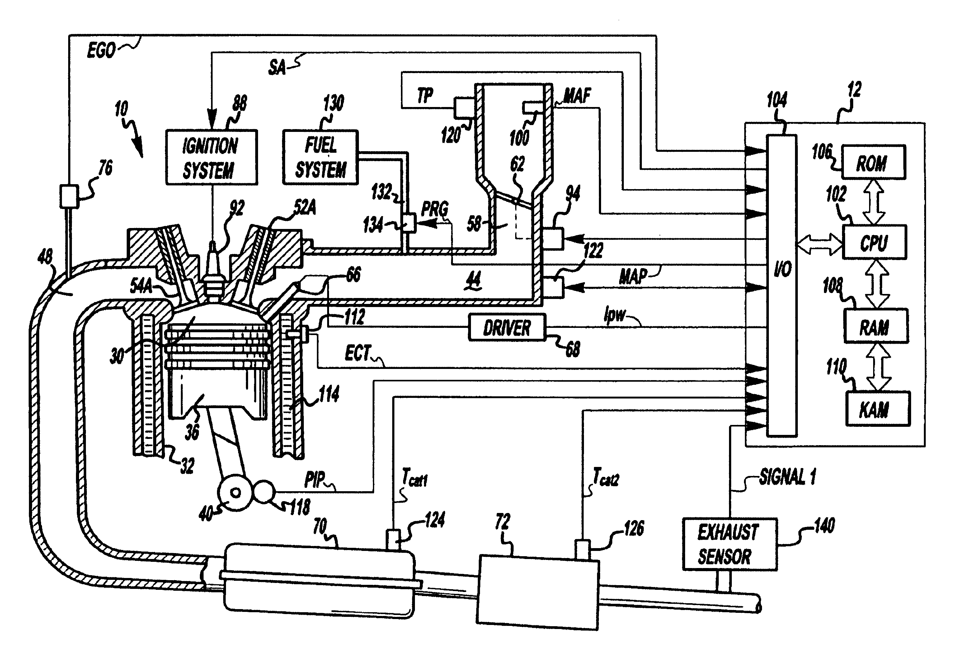
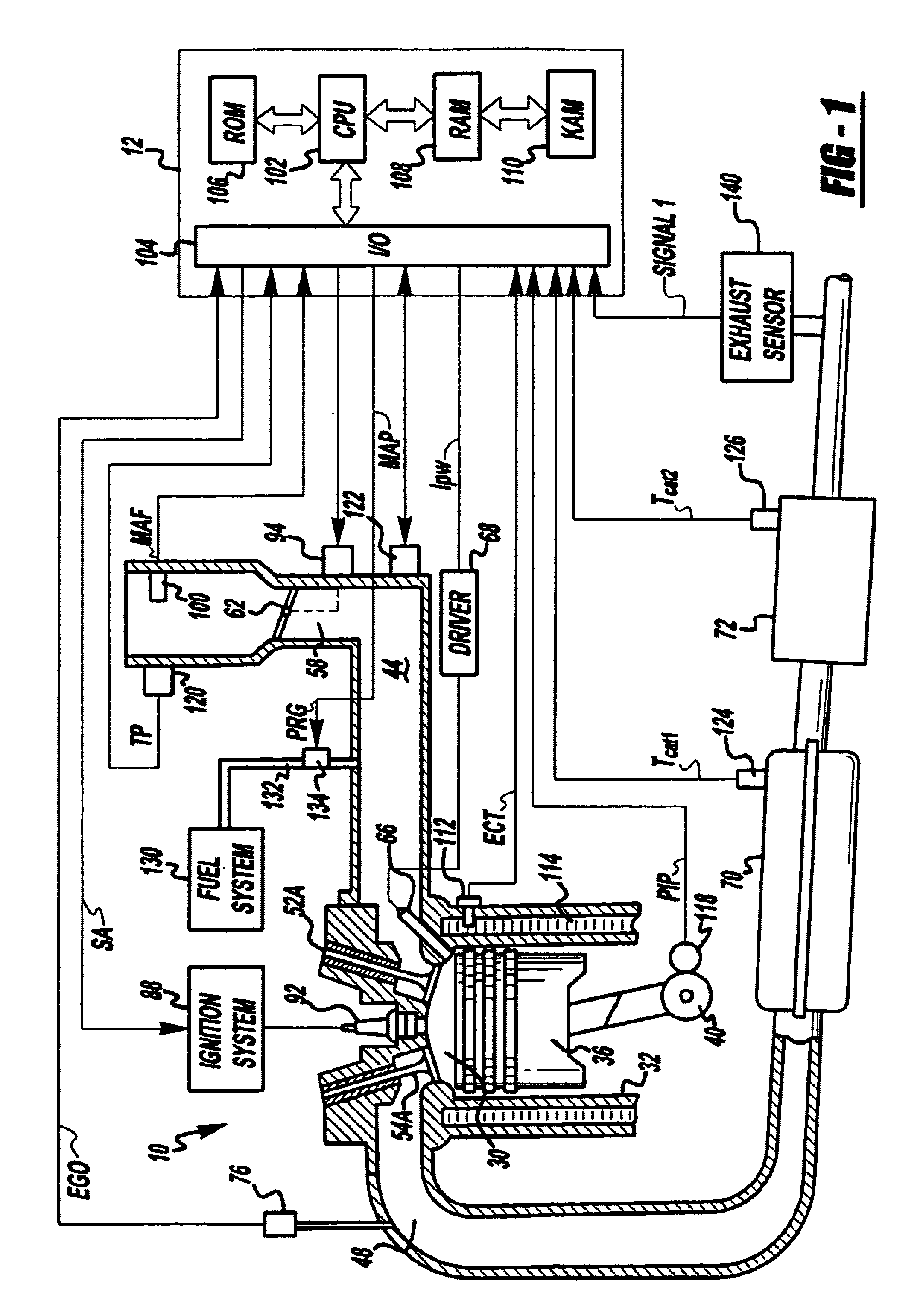
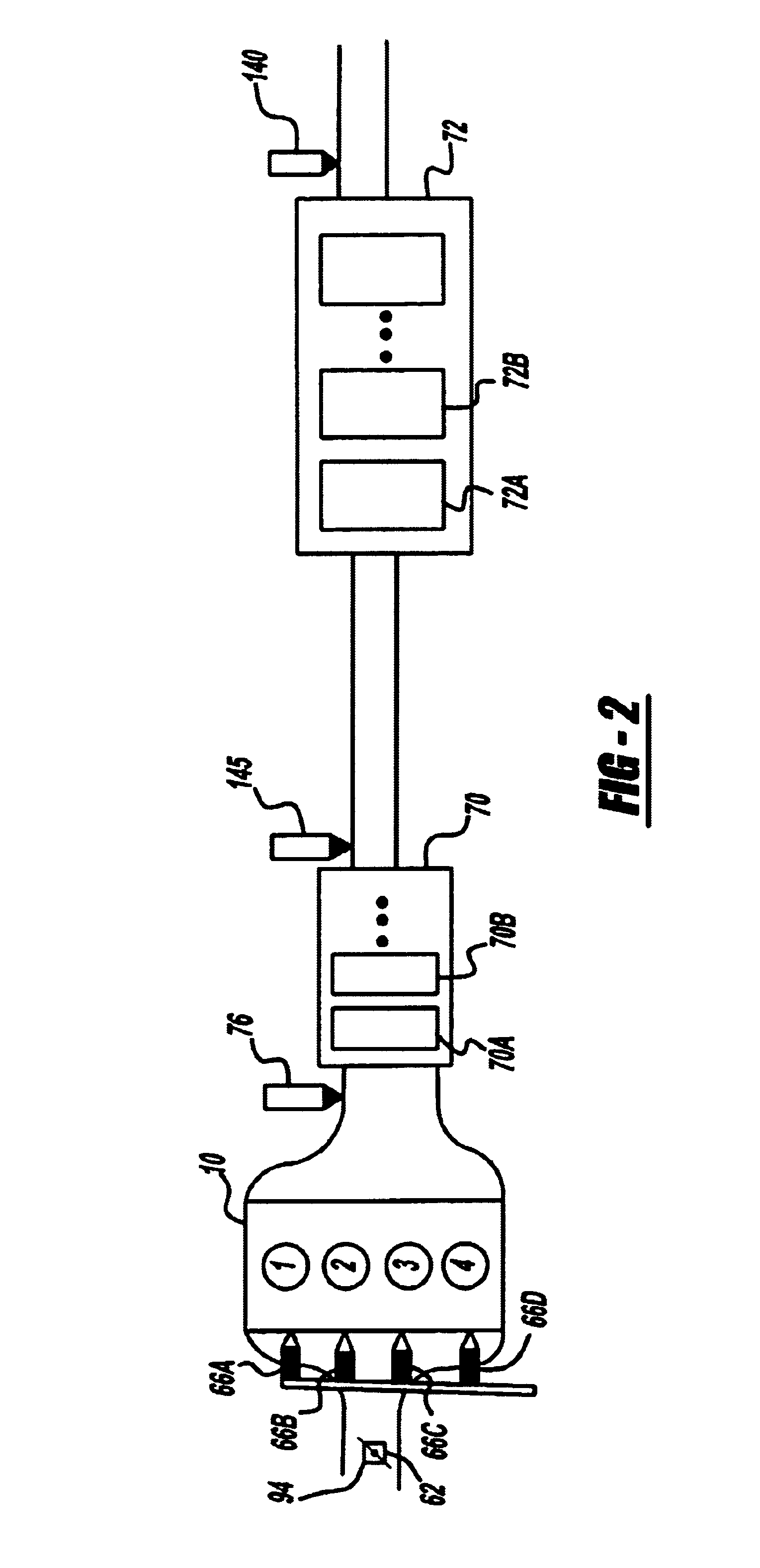
Direct injection spark ignited internal combustion engine 10, comprising a plurality of combustion chambers, is controlled by electronic engine controller 12 as shown in FIG. 1. Combustion chamber 30 of engine 10 includes combustion chamber walls 32 with piston 36 positioned therein and connected to crankshaft 40. In this particular example, piston 30 includes a recess or bowl (not shown) to help in forming stratified charges of air and fuel. Combustion chamber 30 is shown communicating with intake manifold 44 and exhaust manifold 48 via respective intake valves 52a and 52b (not shown), and exhaust valves 54a and 54b (not shown). Fuel injector 66 is shown directly coupled to combustion chamber 30 for delivering liquid fuel directly therein in proportion to the pulse width of signal fpw received from controller 12 via conventional electronic driver 68. Fuel is delivered to fuel injector 66 by a conventional high pressure fuel system,(not shown) including a fuel tank, fuel pumps, and ...


PUM


Abstract

A microprocessor-based controller is provided for generated heat in at various locations in an exhaust system of an engine by changing the heat generation technique utilized. In one case, some cylinder air-fuel ratios are modulated between stoichiometry and rich, while others are modulated between stoichiometry and lean. Another approach operates some cylinder lean, while others are modulated between a first rich, and a second, less rich, value. Further, compensation based on engine airflow is also provided. Finally, various methods are described for temperature control and for controlling modulation of air-fuel ratio.

Description

BACKGROUND OF THE INVENTIONEngines can be coupled to emission control devices, such as catalytic converters, to reduce exhaust emissions. However, these devices can become contaminated with sulfates, for example. In order to remove these contaminates, the temperature of the emission control device is raised significantly and a near stoichiometric air-fuel ratio is provided that alternates, or oscillates, around stoichiometry (between lean and rich).One type of engine exhaust system routes all of the engine cylinders into a single exhaust path. One approach for raising temperature of such a single exhaust path sequentially operates some cylinders lean, and then some rich to create heat. Such an approach is described in U.S. Pat. No. 5,974,788, for example.The inventors herein have recognized numerous disadvantages with such an approach In particular, even with ignition timing adjustments, it is difficult to reduce torque disturbances due to the air-fuel ratio transitions across stoic...

Claims


Application Information

Patent Timeline
Patent Type & Authority Patents(United States)
IPC IPC(8): F01N3/08F02D41/02F02D41/18F02D41/14F02D41/34F01N7/04F01N7/00F01N7/02F02M25/07F01N13/02F01N13/04F02D41/00
CPCF01N3/0814F01N13/011F02D41/0082F02D41/0245F02D41/1475F02D41/182F01N13/0097F01N13/0093F01N13/009F01N3/0842F01N13/107F02D41/1408F02D41/1441F02D2200/0406F02D2200/0802Y02T10/26Y02T10/12
Inventor ELWART, SHANESURNILLA, GOPICHANDRA
Owner FORD GLOBAL TECH LLC
Why Eureka
Try Eureka