
Control unit gear or shift program selection of an automatic vehicle gearbox

a technology of automatic transmission and control unit, which is applied in the direction of mechanical control devices, anti-theft devices, manual control with single controlling member, etc., and can solve the problem of no longer being able to move the vehicl

Inactive Publication Date: 2005-02-08
ZF FRIEDRICHSHAFEN AG
View PDF18 Cites 25 Cited by
  • Summary
  • Abstract
  • Description
  • Claims
  • Application Information

AI Technical Summary

Benefits of technology

The object of the present invention is therefore to improve a control unit of this type such that release of the parking brake is provided, which supports the theft protection measures currently used in motor vehicles, and is also designed in terms of its operation such that the operating devices that are present individually and are commonly used in the state of the art for the emergency release mechanism of the parking brakes of motor vehicle automatic transmissions can be eliminated.
Due to the operating device of the emergency release mechanism being fully integrated, manufacturing and assembly costs for the separate arrangement of the elements of the emergency release mechanism are saved, on the one hand, and, moreover, the integration leads to a reduction of necessary operating elements for the driver and thus to an ergonomically more favorable, clearer handling of the motor vehicle transmission. Moreover, the usual requirements currently imposed in terms of theft protection are taken into account to the fill extent due to the coded release mechanism of the stop element.
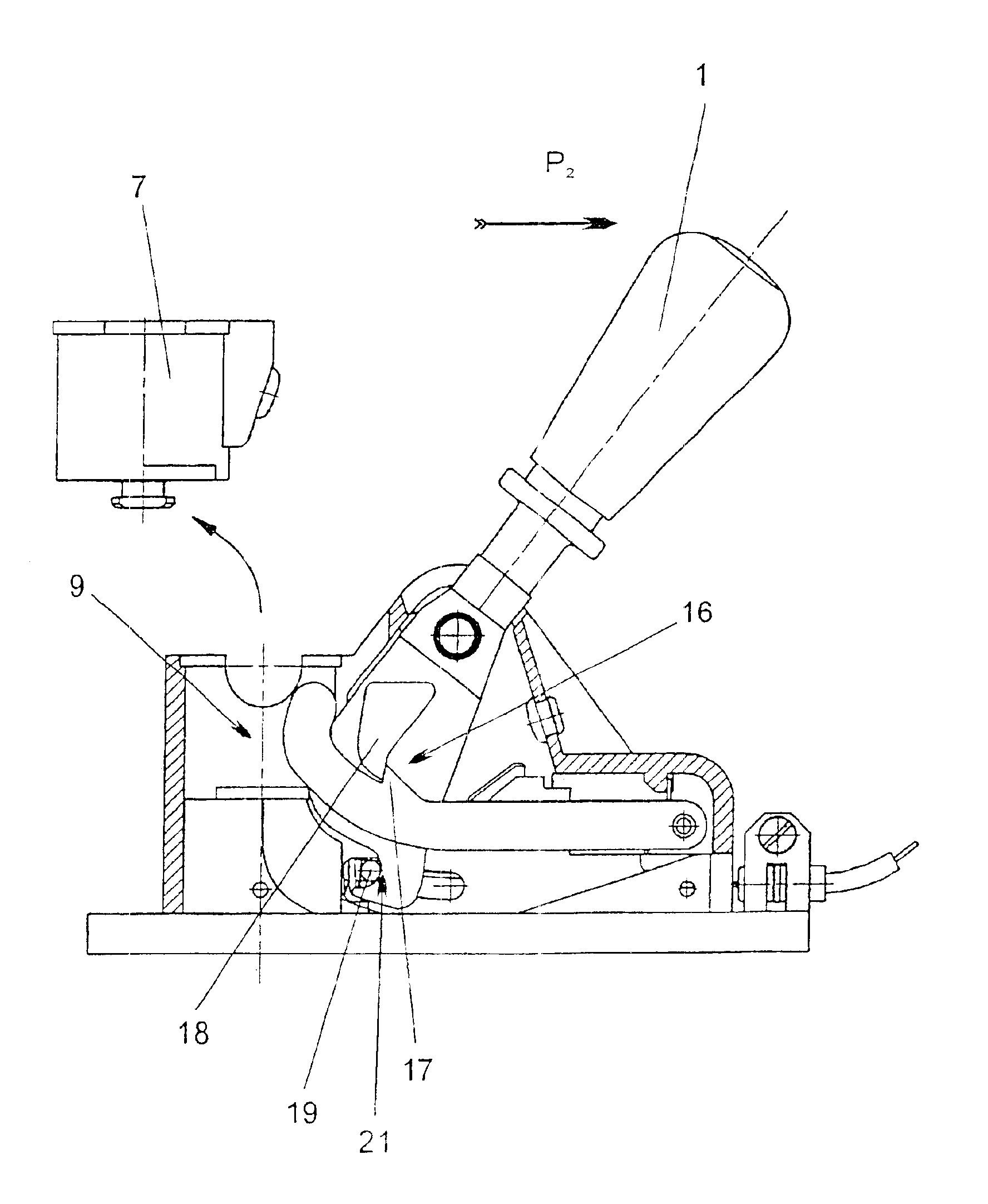
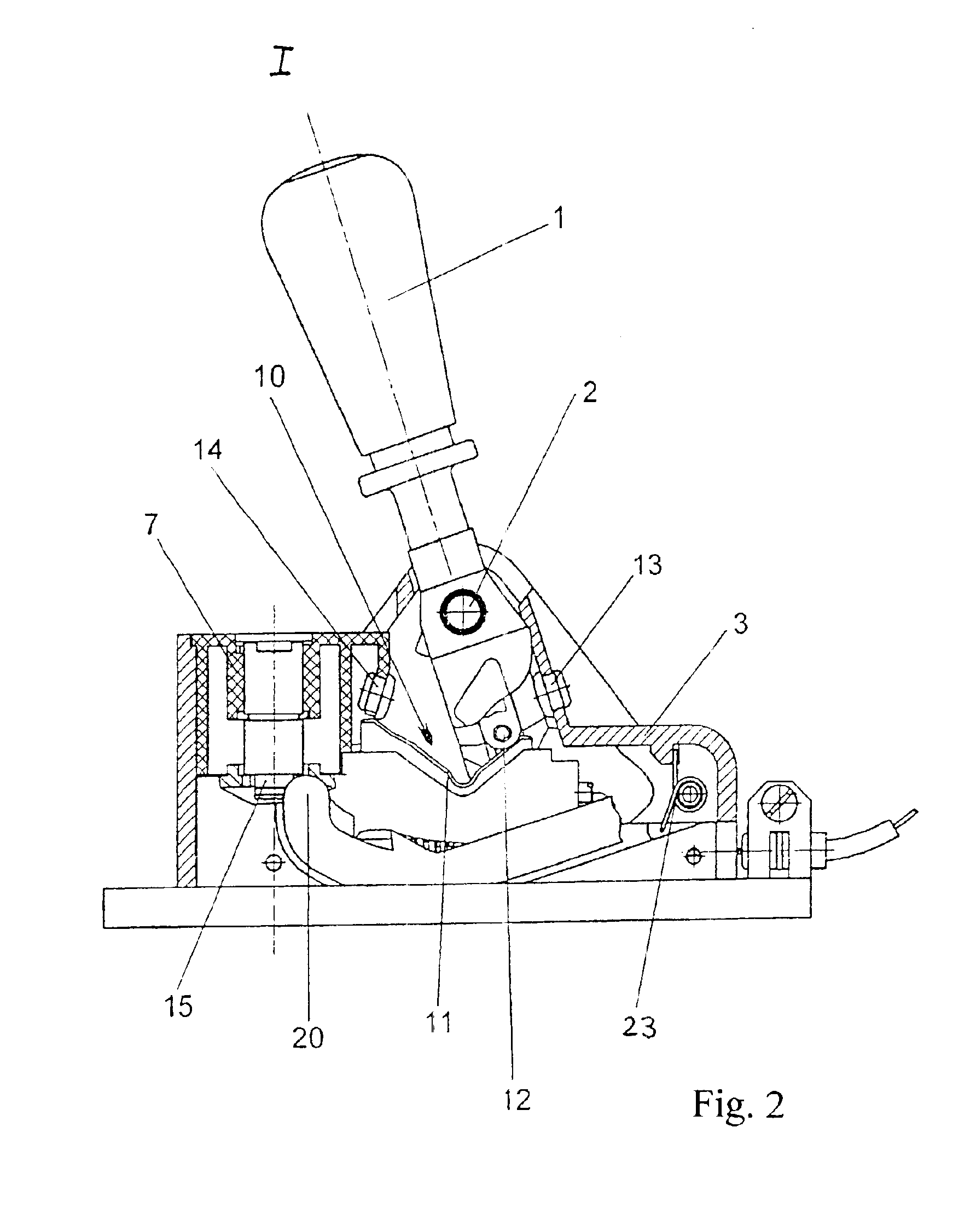
Corresponding to an advantageous variant of the subject of the present invention, the control element may be designed as a carrier, which engages a hook-shaped recess on the selector lever as soon as the latter has been brought into the release position for the parking brake, i.e., into the emergency release position. The carrier may be coupled with the parking brake by means of, e.g., a cable acting as a connection member, but the present invention is, of course, not limited to this, because any mechanical connection is possible. The mechanical embodiment offers an inexpensive possibility of variation according to the present invention.
It proved to be advantageous for other fields of application for the control element to be provided with a Hall sensor system at the selector lever, where the control signal generated by the Hall sensor system comprising a Hall sensor and the corresponding permanent magnet is to be considered to be an information and monitoring signal for the position of the parking brake.
The latter embodiment variant offers especially the advantage that the emergency release position of the gearshift lever can be additionally transmitted to the motor vehicle transmission via the control lines already present in shift-by-wire shifting mechanisms.
Furthermore, a variant of the present invention, in which a locking device is arranged in the housing of the control unit for fixing the operating device in the release position for the parking brake is arranged, proved to be advantageous. The locking device ensures that during the towing of the vehicle, during which the operating device, preferably the selector lever, is brought into the emergency release position, the selector lever remains in the selected position, and relocking of the parking brake during towing is thus ruled out. The locking device may advantageously comprise here a ratchet lever mounted rotatably in the housing with a recess and a detent arranged in a fixed position at the selector lever, where the recess and the detent are engaged in the parking brake release position of the selector lever.

Problems solved by technology

If the park position is selected on the automatic transmission by means of the control unit, blocking is brought about in the transmission by suitable measures, so that movement of the vehicle is no longer possible when the park position is engaged.

Method used


Image

  • Control unit gear or shift program selection of an automatic vehicle gearbox
  • Control unit gear or shift program selection of an automatic vehicle gearbox
  • Control unit gear or shift program selection of an automatic vehicle gearbox

Examples


Embodiment Construction

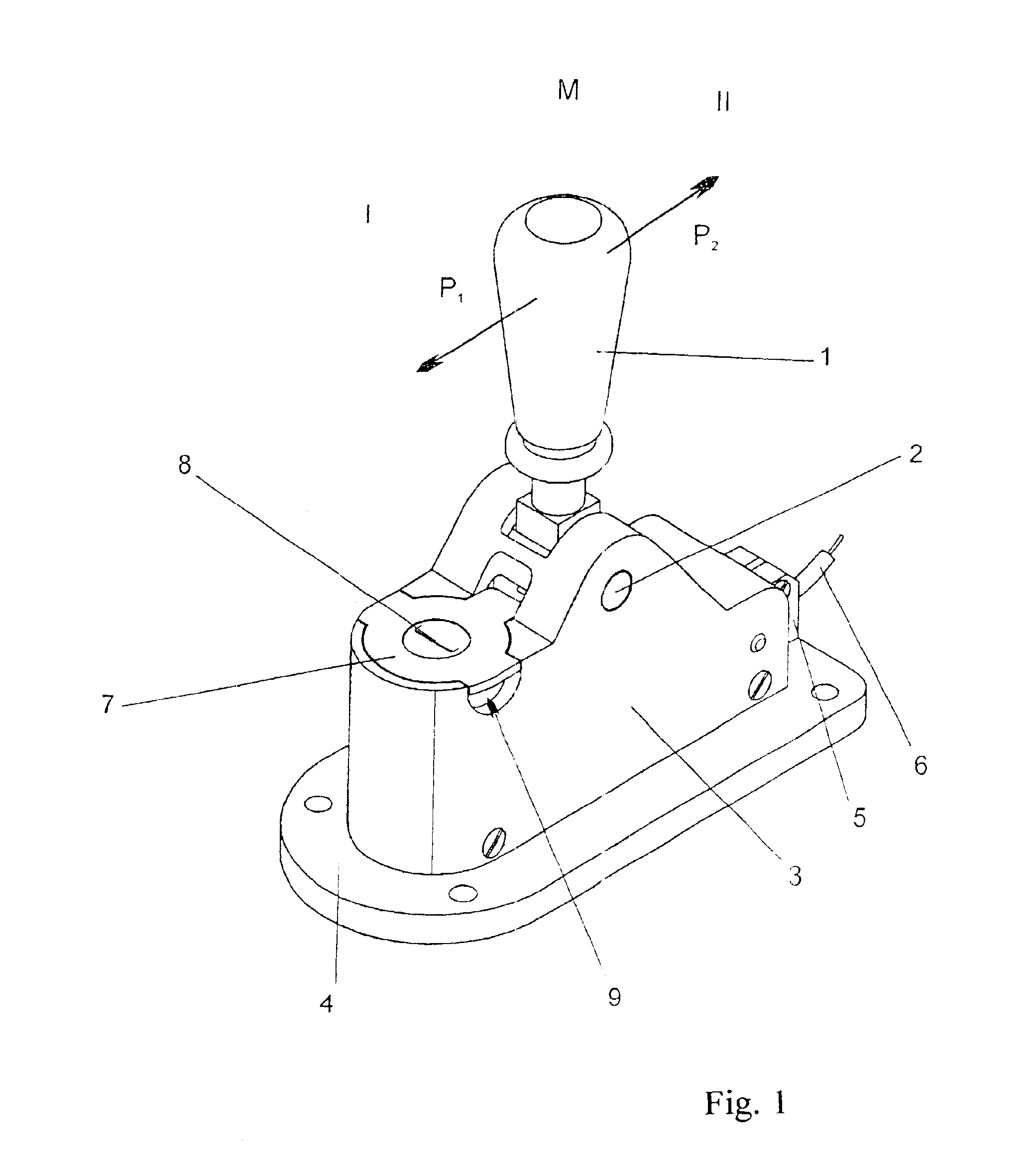
Referring to the drawings in particular, the control unit for the gear or shift program selection of a motor vehicle automatic transmission, which is shown in a perspective view in FIG. 1 has a selector lever 1, which is arranged pivotably around an axis of rotation 2 in a housing 3 of the control unit. On the lower side of the housing 3 facing away from the selector lever, the housing is provided with a base 4, which is used to fasten the control unit on a body-side mount of a motor vehicle, which said mount is not shown in detail. The selector lever 1 can be moved in the longitudinal direction of the housing 3 corresponding to the arrows P1 and P2 because of it being mounted by means of the axis of rotation 2, so that there are two lateral end positions I and II besides the middle position of the selector lever 1 shown in FIG. 1.

FIG. 1 also shows that a holding element 5 for a cable 6 is arranged at the longitudinal end of the control unit. The holding element 5 is used to fix and...


PUM


Abstract

A control unit for the gear or shift program selection of an automatic transmission of a motor vehicle is presented, which has a emergency release mechanism. With this a parking brake of the motor vehicle transmission can be released by an operating device that can be actuated by the driver. A housing (3) is provided and a selector lever (1), which can be brought into at least two end positions, in which control unit the operating device of the emergency release mechanism is an integral part of the control unit, and in which the operating device has a detachable stop element (7). The stop element (7) is secured in a mount (9) of the control unit by means of a coded release mechanism (15) and acts as a movement limitation for the release movement of the parking brake by the operating device of the emergency release mechanism in the non-actuated state. The emergency release mechanism can also be actuated due to this novel design even with the control unit only, and, moreover, increased requirements on theft protection can be met.

Description

FIELD OF THE INVENTIONThe present invention pertains to a control unit for the gear or shift program selection of a motor vehicle automatic transmission, which has an emergency release mechanism, by which a parking brake of the motor vehicle transmission can be released by means of an operating device that can be operated by the driver, with a housing and with a selector lever that can be brought into at least two end positions.BACKGROUND OF THE INVENTIONAutomatic transmissions, for which the operating unit of this type can be used, usually have a plurality of operating steps, which can be manually preselected by the driver and are called gears. One of the operating steps of an automatic transmission is a so-called park position. If the park position is selected on the automatic transmission by means of the control unit, blocking is brought about in the transmission by suitable measures, so that movement of the vehicle is no longer possible when the park position is engaged.However,...

Claims


Application Information

Patent Timeline
IPC IPC(8): F16H59/10F16H61/22B60K20/02
CPCF16H59/10F16H61/22Y10T74/2014F16H2061/223Y10T74/20073F16H2061/226Y10T70/5925
Inventor MEYER, JORGRAKE, LUDGER
Owner ZF FRIEDRICHSHAFEN AG
Learn More