
Light source device for pumping solid-state laser medium

a laser medium and light source technology, applied in the direction of lasers, semiconductor laser arrangements, semiconductor lasers, etc., can solve the problems of complicated wiring of lead leads for ld bars, difficult to solve heat, leakage of coolant, etc., and achieve the effect of compact structure and easy maintenan

Inactive Publication Date: 2005-02-01
FANUC LTD
View PDF16 Cites 9 Cited by
  • Summary
  • Abstract
  • Description
  • Claims
  • Application Information

AI Technical Summary

Benefits of technology

An object of the present invention is to improve a light source device for pumping a solid-state laser medium of a laser generator to be capable of economically using LD bars constituting a LD stack with easy maintenance and have a compact structure.

Problems solved by technology

It is difficult to solve the problem of heat since an efficiency of light emission of the LD is not greater than 50% at present and a driving power thereof not less than 50% is transferred into heat.
In the above arrangement of the pumping light source device, the following problems arise as the number of stacked LD bars increases.
If a large number of cooling devices having reduced thickness are stacked, pressure applied to each of the sealing members is lowered to tend to cause leakage of the coolant.
In this arrangement, however, conduits for flow passages of the coolant and wiring of leads for the LD bars are made complicated, and a nonradiative area (dead space) produced between the LD stacks is increased to an extent which can not be ignored, to fail in effectively pumping the laser medium.
In the former way, a large number of useable LD bars are wasted in vain and in the latter way, it is difficult to specify the broken LD bar in a large number of stacked LD bars, and even if the broken LD bar is specified the broken LD bar can not be easily replaced with a new one.

Method used


Image

  • Light source device for pumping solid-state laser medium
  • Light source device for pumping solid-state laser medium
  • Light source device for pumping solid-state laser medium

Examples


Embodiment Construction

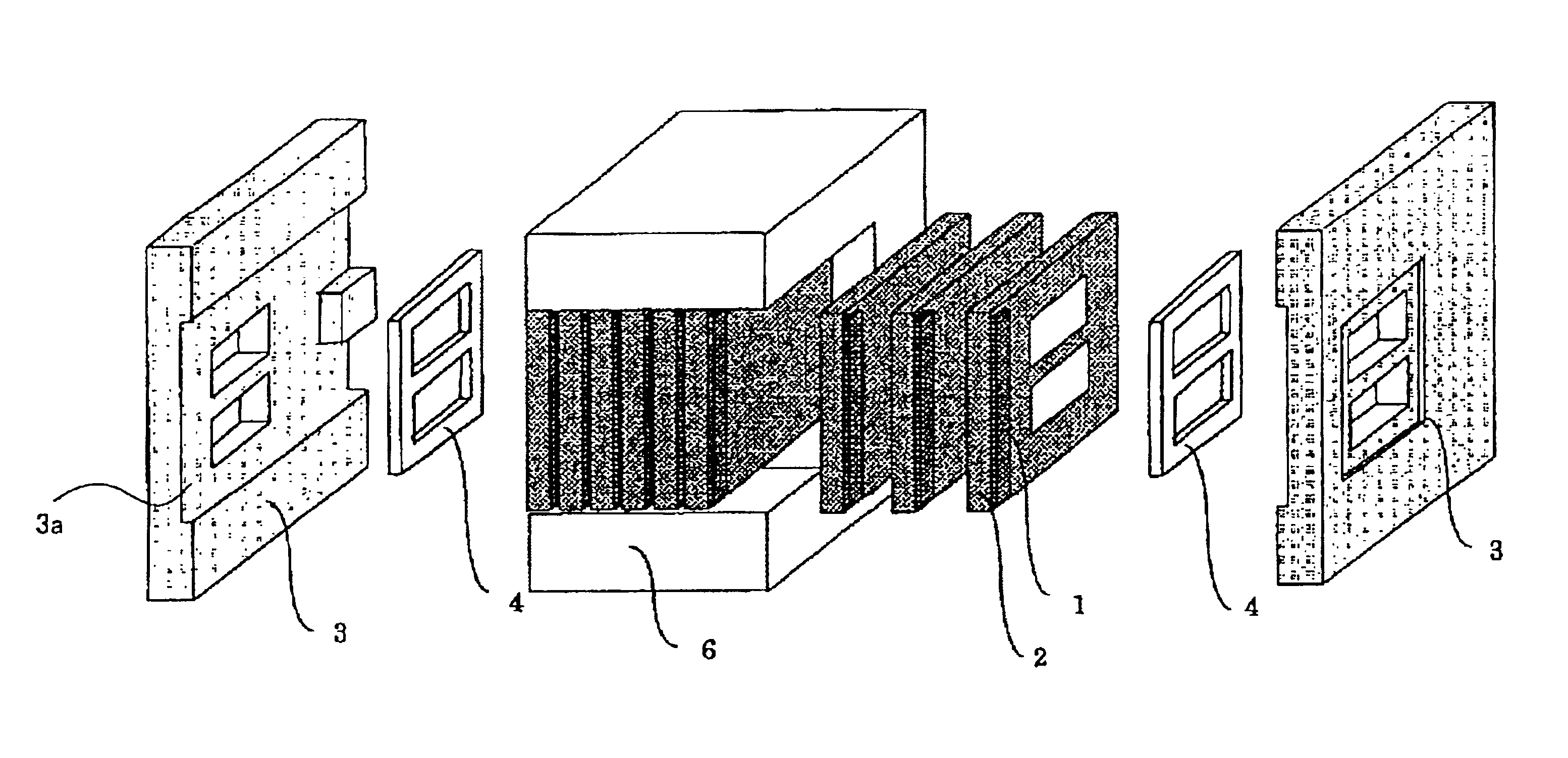
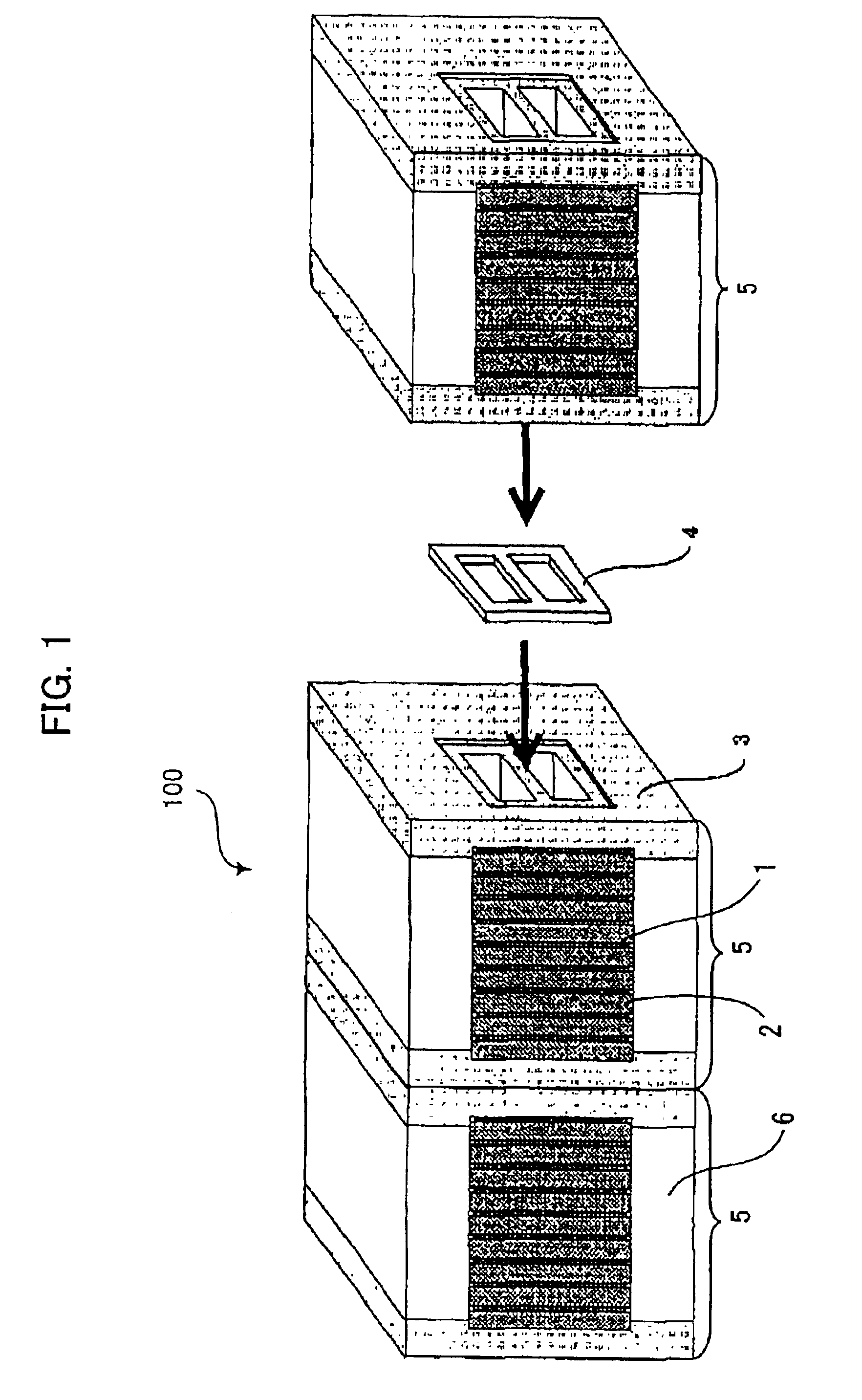
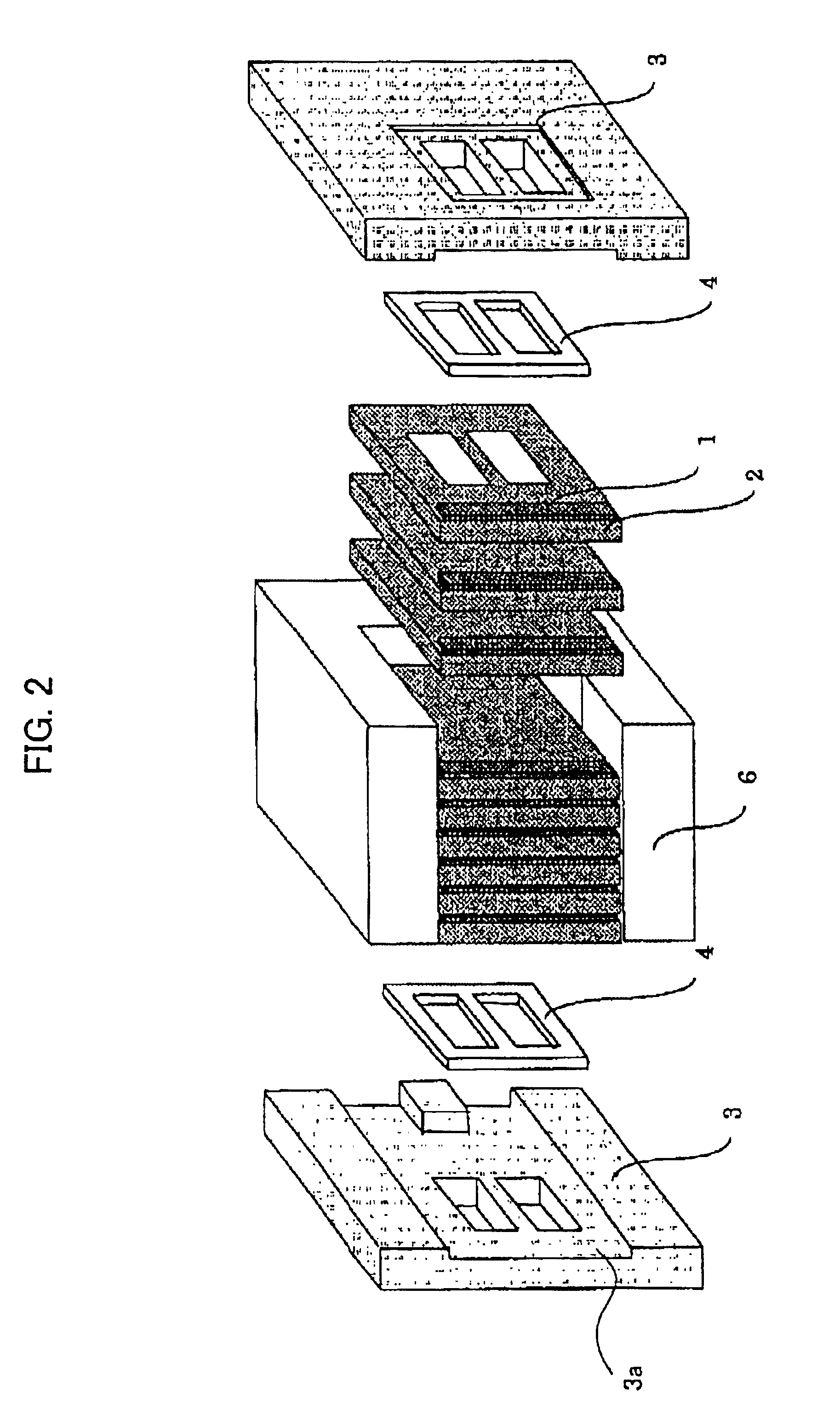
A partly exploded view of FIG. 1 shows a fundamental arrangement of a LD stack for use as a light source device according to an embodiment of the present invention. In FIG. 1, an LD stack 100 comprises a plurality of LD modules 5 of which one LD module 5 is depicted separately form the rest of the LD modules 5 for the sake of illustration. Each of the LD modules 5 comprises a plurality of cooling devices 2 with LD bars 1 respectively mounted thereon, a housing 6 for supporting the cooling devices 2 with the LD bars 1 thereon and the connection plates 3 arranged on both sides thereof. The LD bar 1 is mounted on the cooling device 2 in the vicinity of one peripheral side thereof such that a longitudinal direction of the LD bar 1 extends along the peripheral side of the cooling device 2. The cooling devices 2 are connected with one another such that the LD bars 1 thereon are subsequently stacked in a direction perpendicular to longitudinal directions thereof. In using the LD stack 100 ...


PUM


Abstract

A light source device for pumping a solid-state laser medium of a laser generator, which is compact and capable of economically using LD bars constituting the LD stack with easy maintenance. The light source device is constituted by a plurality of LD modules. Each LD module comprises a plurality of cooling devices on which LD bars are respectively mounted and connection plates on both sides thereof. The LD bars are stacked such that longitudinal directions thereof extend perpendicular to a stacking direction thereof. A desired number of LD modules are mechanically connected with each other using the connection plates to form the LD stack. A sealing member is intervened between confronting connection plates of adjacent LD modules, so that flow passages of coolant formed in the respective LD modules are continuously connected. The connection plates have functions of fixedly supporting the cooling devices of each LD module and electrically connecting the adjacent LD modules.

Description

BACKGROUND OF THE INVENTION1. Field of the InventionThe present invention relates to a light source device using semiconductor laser (laser diode) for pumping a solid-state laser medium of a high-power solid-state laser generator suitable for use in a laser machining apparatus.2. Description of the Related ArtIn recent years, a solid-state laser generator such as YAG laser is generally used in a laser machining apparatus for cutting, welding, etc. of metal and nonmetal material. A semiconductor laser (laser diode) as well as conventional lamps are adopted as a light source for pumping a solid-state laser medium of the laser generator.The pumping by the laser diodes (LD) is expected to be mainly used in the near future in view of advantages thereof. Particularly, it is possible to make a wavelength of a pumping light substantially coincide with a light absorbing range of the solid-state laser medium in the LD pumping, to enhance efficiency of energy absorption of the solid-state lase...

Claims


Application Information

Patent Timeline
IPC IPC(8): H01S5/40H01S3/0941H01S5/00H01S5/024H01S3/094H01S3/042
CPCH01S3/0941H01S5/4025H01S5/02423
Inventor TAKIGAWA, HIROSHINISHIKAWA, YUJISATO, MASAONAITO, SHINYAMIYATA, RYUSUKE
Owner FANUC LTD
Learn More