
Tie down bar

Inactive Publication Date: 2005-02-01
HUSK VERNON R
View PDF29 Cites 27 Cited by
  • Summary
  • Abstract
  • Description
  • Claims
  • Application Information

AI Technical Summary

Benefits of technology

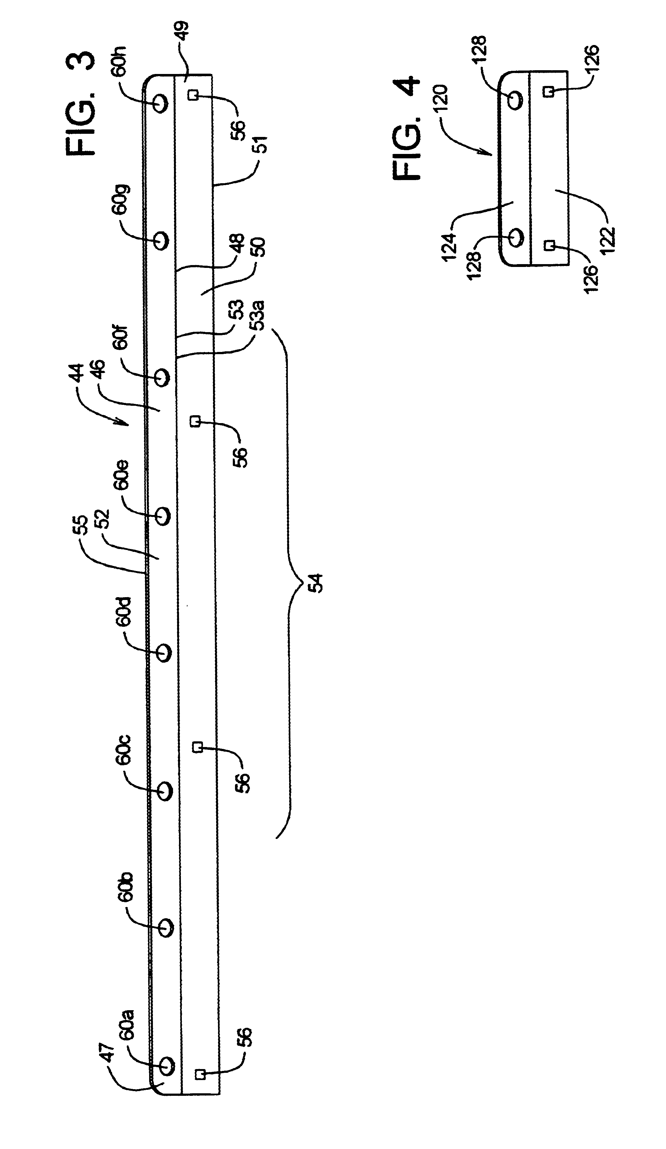
A bracketing member for use with mounting straps is adapted to be mounted to the upper forward region that is substantially vertical of the bed of a truck. The truck has a longitudinal and lateral axis and adapted to mount a motorcycle having a front tire thereto. The bracketing member comprises elongate member adapted to substantially extend in the lateral direction having a central region. The elongate member comprises a mounting region substantially extending in the lateral direction and substantially planar in a mounting plane and having a plurality of mounting points that comprise surfaces to define openings. The mounting region is adapted to be mounted to said upper forward region of the bed of a truck. The elongate member further comprises an attachment region extending in an attachment plane that is non-coplanar to the mounting region so as to provide rigidity. The attachment region has a plurality of positionally fixed attachment points that define openings that are no larger than 3 inches in any direction. The attachment points are adapted to connect to the mounting straps and the attachment plane is adapted to be within 25 degrees of the direction of pull of the mounting straps. A plurality of fasteners having a head region, a base region and a linking member are used where the fasteners are adapted to mount the elongate member removably and mechanically to the upper forward region of the truck bed at the mounting points of the elongate member. The mounting region is adapted to distribute the load exerted upon the elongate member for a substantially more uniform load distribution along the said upper forward region of the bed of a truck.

Problems solved by technology

Riding up a ramp requires a fair degree of skill depending upon the height of the pickup truck and length of the ramp, but oftentimes this can be a difficult task, particularly for inexperienced rider.
This is particularly dangerous because oftentimes the ramp has insufficient lateral width and if the rider were to stop halfway up there is no suitable area in the lateral direction to support the rider.
Oftentimes, an impact from the front tire of a motorcycle may cause a dent in the front region of the truck bed depreciating the truck's value.

Method used


Image

  • Tie down bar
  • Tie down bar
  • Tie down bar

Examples


Embodiment Construction

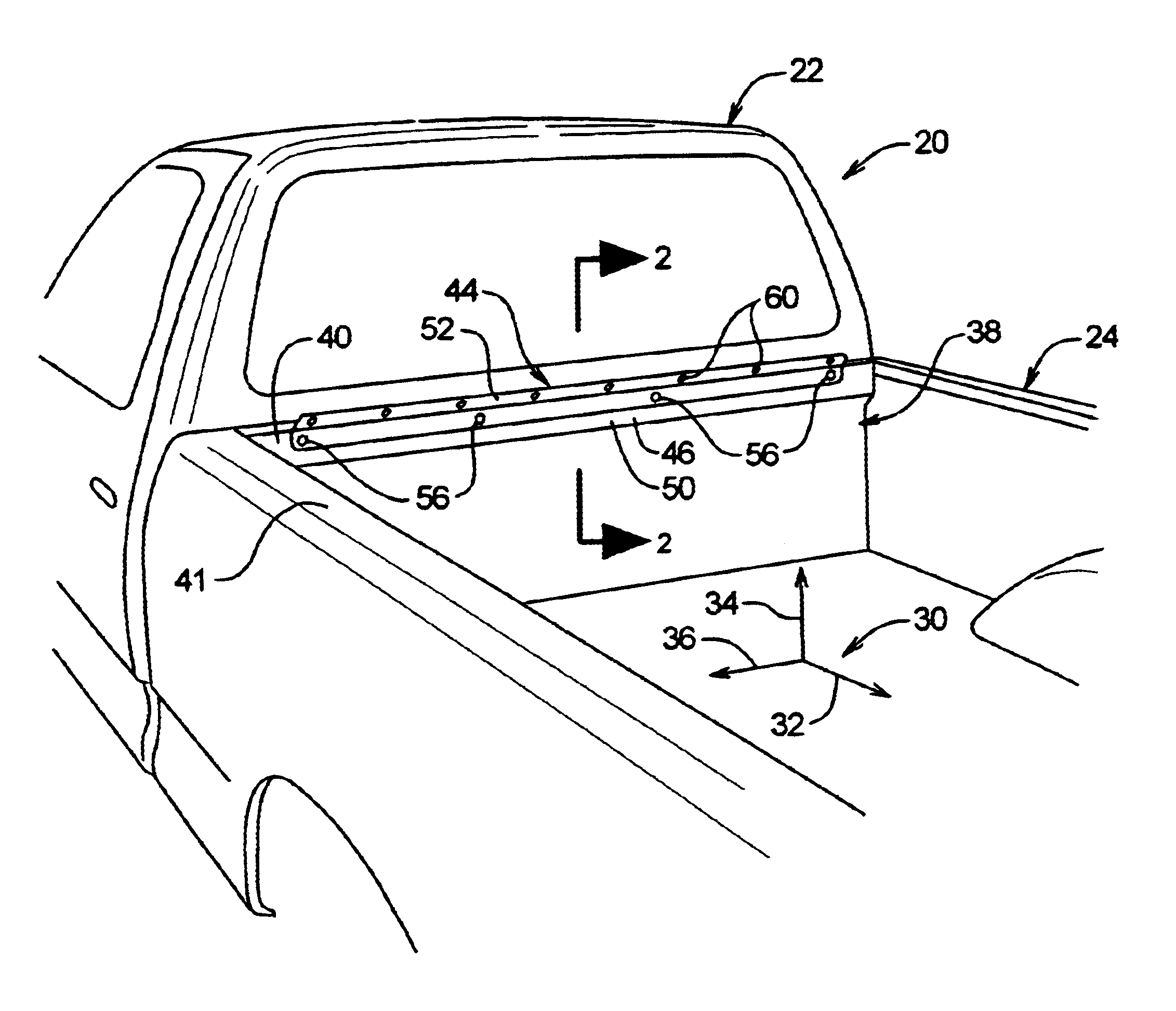
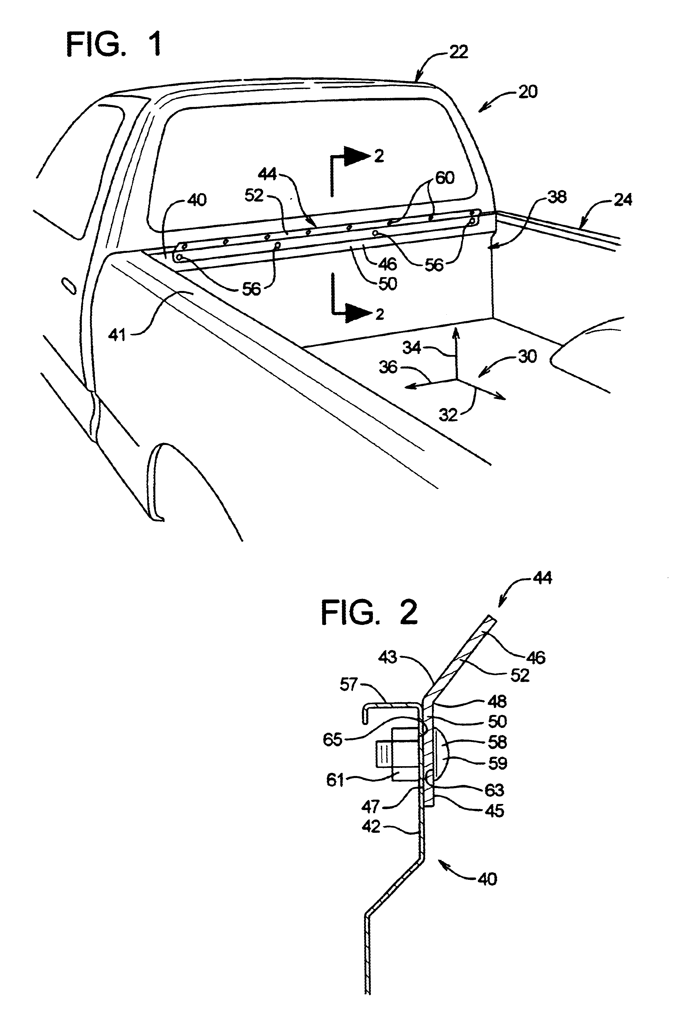
There will now be a discussion of the present invention with initial reference to FIG. 1. As shown in this figure, the general environment is a truck 20 having a cab region 22 and a bed region 24. To assist the description of the invention an axis system 30 is defined to indicate general directions. The axis 32 indicates a longitudinal direction. The axis 34 indicates a vertical direction and the axis 36 indicates a lateral direction. The directions are not intended to limit the invention to any specific orientation other than the limitations set out in the claims. The bed region 24 of the truck 20 has a forward region 38 and located in the forward region is an upper region indicated at 40. As shown in FIG. 2, the upper forward region 40 of the truck bed 24 generally has a relatively thin side profile made usually from a metallic material indicated at 42 and is commonly formed by a stamping or bending process described further herein. Normally, the rigidity of the upper forward regi...


PUM


Abstract

A bracketing member adapted to mount a motorcycle to the upper forward region of the bed of a pickup truck with mounting straps. The bracketing member having an elongate member adapted to extending in the lateral direction and having a mounting region and an attachment region that are not coplanar to provide rigidity. The plane that the attachment region is positioned in a substantially in line with the direction of pull of the mounting straps.

Description

BACKGROUND OF THE INVENTIONa) Field of the InventionThe invention relates to a tie down bar, particularly a bar that is adapted to be retrofitted to pickup trucks. It is common practice to mount motorcycles or the like to the bed region of a pickup truck. Oftentimes, pluralities of motorcycles are desired to be attached to a pickup truck and there are limited fixing points to attach the mounting straps to pickup. Alternately, there are no suitable mounting locations to attach the mounting straps (e.g. tie downs). An additional problem associated with mounting a motorcycle to the bed region of a pickup truck is oftentimes a substantial amount of force is exerted upon the mounting straps where the front shock of the motorcycle is compressed and the mounting straps have a relatively high amount of tension exerted thereon. This tension is transferred to the mounting point of the pickup truck which oftentimes is a single point load. Further, an opposite longitudinally forward force is ex...

Claims


Application Information

Patent Timeline
IPC IPC(8): B60R9/00B60R9/10B60P3/079B60P3/06
CPCB60R9/10B60P3/079
Inventor HUSK, VERNON R
Owner HUSK VERNON R
Learn More