Fishing reel bearing and component support structure

a technology of supporting structure and reel bearing, which is applied in the direction of bearing components, shafts and bearings, reels, etc., can solve the problems of poor sealing performance, degrading rotational performance, and and achieves low corrosion resistance. ingredient, the effect of low corrosion resistance of the parent material

Inactive Publication Date: 2005-02-01
SHIMANO INC
View PDF18 Cites 18 Cited by
  • Summary
  • Abstract
  • Description
  • Claims
  • Application Information

AI Technical Summary

Benefits of technology

A fishing-reel bearing in terms of the sixth invention is the bearing set forth in the fifth invention, wherein at least the rolling bodies are low corrosion-resistant-ingredient SUS 440C manufactures. In this case, the corrosion resistance of the parent material is inferior, but the parent material strength is high, which lengthens the life span of the bearing.
A fishing-reel component support structure in terms of the seventh invention is a structure for supporting in a fishing reel, and letting rotate relative to each other, a first component and a second component, and is furnished with a bearing and a sealing member. The bearing is any set forth in inventions one through six, disposed in a position within the reel in which liquids from the exterior can invade. The sealing member is disposed to the side opposite the side where liquid invades through the bearing, and is a member that seals the clearance between the two components. In this case, though seawater invades the bearing it is not liable to corrode, and at the same time rinse water or the like can permeate the bearing, which facilitates washing a sea-water soiled bear

Problems solved by technology

Nevertheless, a problem with SUS440C is that, compared to austenites such as grade SUS304 and SUS316 among carbon steels, though it is harder its corrosion resistance is lower.
Preventing corrosion with a sealed bearing will mean that the sealing element contacting the inner/outer races places a higher rotational load on the bearing, which degrades rotational performance.
To sustain rotational performance a non-contact sealing element c

Method used


Image

  • Fishing reel bearing and component support structure
  • Fishing reel bearing and component support structure
  • Fishing reel bearing and component support structure

Examples


first embodiment

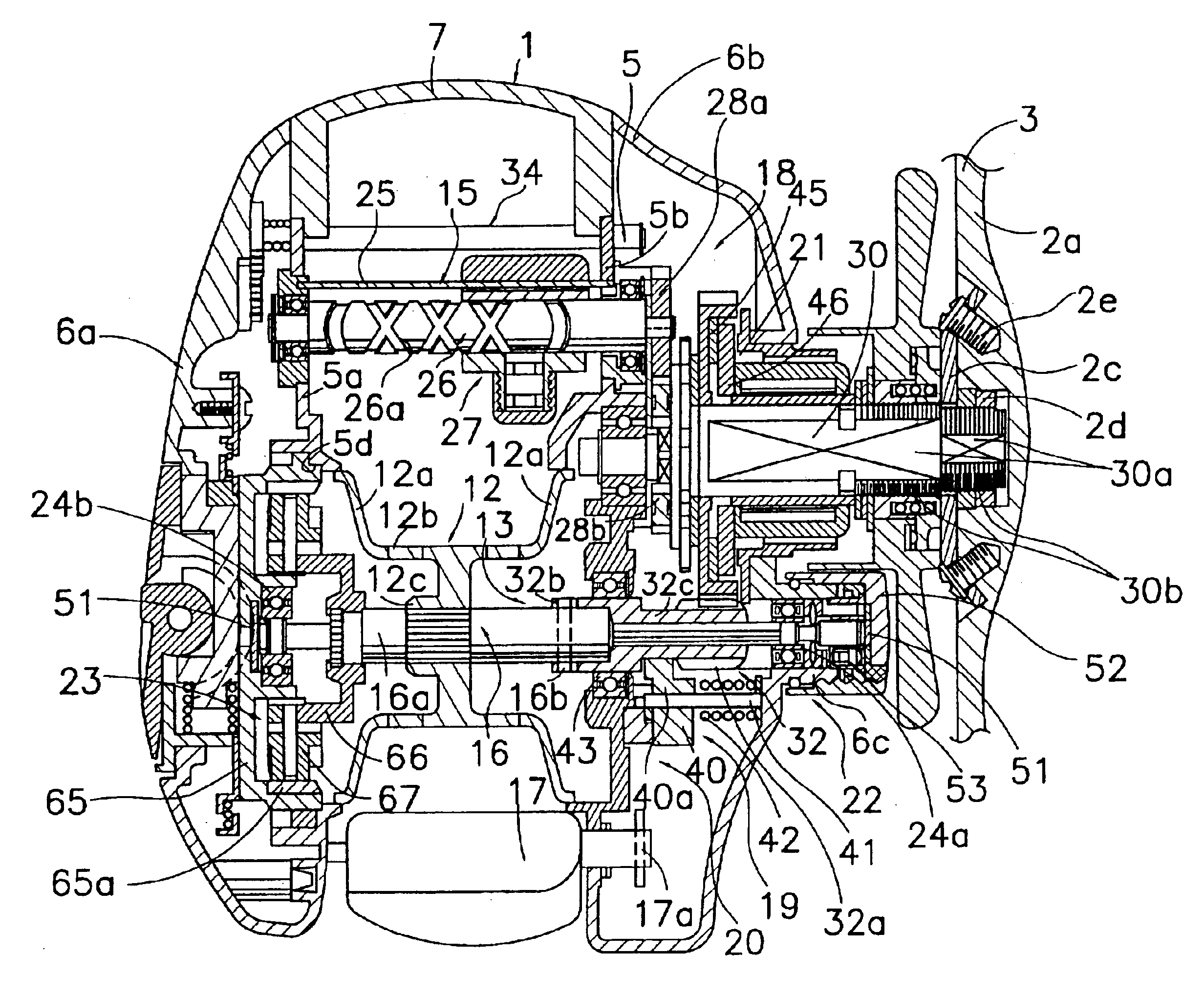
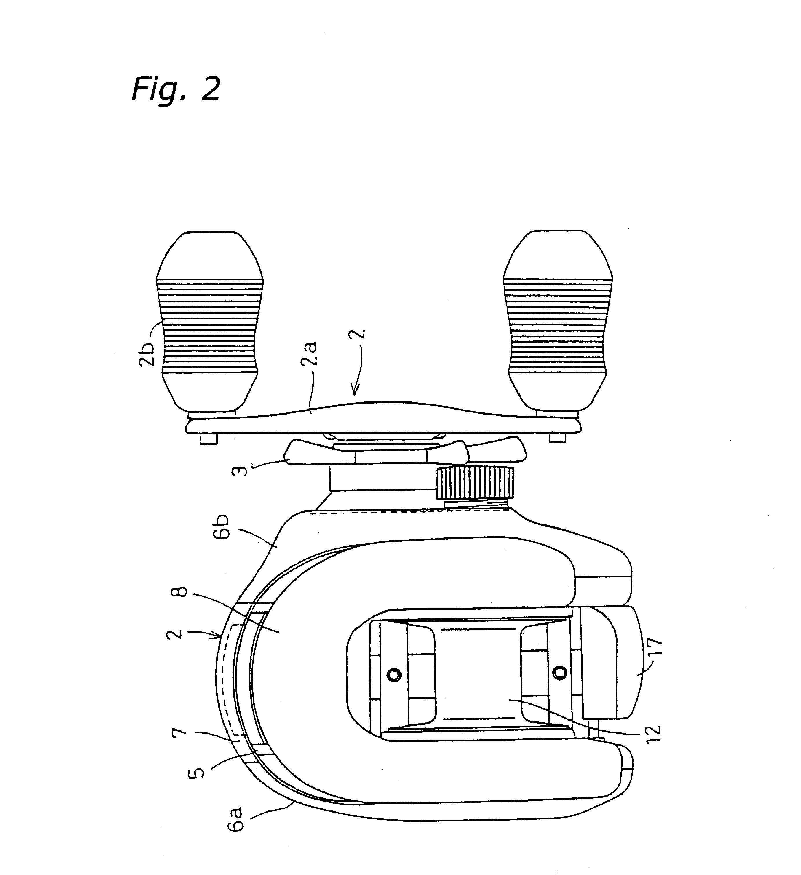
The dual-bearing reel, in which one embodiment of the present invention is adapted, set out in FIG. 1 and FIG. 2, is a baitcasting, low-profile type reel. The reel is furnished with: a reel body 1; a spool-cranking handle 2 disposed sideways on the reel body 1; and a line-winding spool 12 fitted rotatably and detachably / reattachably to the reel body 1 interior. A star drag 3 for adjusting drag tension on the spool 12 is provided on the handle 2 side of the reel body 1.

The handle 2 is in the form of a double handle having a plate-shaped handle arm 2a and grips 2b fitted free to rotate on either end of the handle arm 2a. The handle arm 2a, as shown in FIG. 3, is fixed by two screws 2e to a washer 2c, which is itself fixed non-rotatably to the tip of a handle shaft 30 by a nut 2d. The nut 2d is housed in and stopped against turning by the interior of the handle arm 2a. This configuration leaves the outside face of the handle arm 2a a smooth surface absent of joint seams, meaning that t...

second embodiment

The present invention, which in the foregoing first embodiment was illustrated by giving an example in a dual-bearing reel as a fishing reel, is yet applicable to other fishing reels such as spinning reels.

Set out in FIG. 8, a spinning reel into which one embodiment of the present invention is adopted is furnished with a handle 101, a reel unit 102 rotatively carrying the handle 101, a rotor 103, and a spool 104. The rotor 103 is rotatively supported on the front of the reel unit 102. The spool 104, onto the circumferential surface of which fishing line is retrieved, is disposed on the front of the rotor 104 so as to be shiftable front and rear. In this embodiment, the reel unit 102 functions as a stationary component, while the rotor 103 functions as a rotative component.

The handle 101, as shown in Fig 8 and FIG. 9, includes: a T-shaped grip 101a; an L-shaped crank arm 101b, to the tip of which the grip 101a is rotatively fitted; and a shaft part 101c that is fitted to the base-end...

third embodiment

Set out in FIG. 11, a trolling reel into which a third embodiment of the present invention is adopted is composed of: a tubular reel unit 201; a spool shaft 202 fitted, non-rotatably but allowed axial travel, in the center of the reel unit 201; a spool 203 fixed, free to rotate but axially immobilized, on the spool shaft 202; and a handle 204 disposed sideways on the reel unit 201. In the interior of the reel unit 201, the trolling reel is further furnished with a gear change-speed mechanism 206 that transmits handle 204 rotation to the spool 203, and a drag mechanism 207 that brakes the spool 203. In this embodiment, the reel unit 201 and the spool shaft 202 function as the stationary components, while the spool 203, the handle 204, and the drag mechanism 207 function as rotative components.

The reel unit 201 has a disk-shaped side plate 210, and a reel body 211, onto which the side plate 210 is coupled coaxially through a faucet joint, and fixed by screws. The spool shaft 202 is su...


PUM


Abstract

Fishing reel bearings curtail deterioration in rotational performance, and improve anti-corrosiveness, as well as make it easier to wash the bearings without incurring internal component corrosion. Dual-bearing reel bearing—a bearing provided between a boss, and a spool shaft disposed to the circumferentially inner side of, and rotational relative to, the boss—is furnished with an outer race, an inner race, and a plurality of rolling bodies. The outer race is fitted into the boss. The inner race is fitted in the spool, disposed parted at a clearance from the outer race. Between the two races, the rolling bodies of the plurality are disposed, circumferentially spaced and contacting both the races. The outer race, the inner race, and the rolling bodies are SUS 440C manufactures coated with a highly corrosion-resistant film.

Description

TECHNICAL FIELDThe present invention relates to bearings and component support structures; in particular to fishing reel bearings and component support structures that are provided between a first component and second component disposed to the circumferentially inner side of and rotational relative to the first component, in fishing reels such as spinning reels and dual-bearing reels.BACKGROUND ARTNumerous rotary components, such as rotors, spools and handle shafts, that rotate relative to the reel body or against other components are employed in fishing reels such as spinning reels and dual-bearing reels. Support on bearings lets rotary components of this sort rotate in the reel body or against other components. Ball bearings are often used in fishing reels as the bearings that support these rotary components.Because fishing reels are generally used in an atmosphere in which moisture clings to and is liable to corrode ball bearings, improving their resistance to corrosion is desira...

Claims


Application Information

Patent Timeline
IPC IPC(8): A01K89/015A01K89/01A01K89/00F16C33/32F16C33/44
CPCA01K89/00A01K89/015A01K89/01A01K89/011223A01K89/01928A01K89/0193
Inventor HITOMI, YASUHIRO
Owner SHIMANO INC
Why Eureka
Try Eureka