Spark plug

a technology of spark plugs and plugs, which is applied in the direction of spark plugs, machines/engines, mechanical equipment, etc., can solve the problems of increase in the amount of heat the tip receives, and insufficient heat conductivity of the tip, so as to improve the corrosion resistance of the tip, increase the thermal conductivity of the fusion portion, and improve the effect of heat conductivity

Active Publication Date: 2014-11-25
NGK SPARK PLUG CO LTD
View PDF22 Cites 3 Cited by
  • Summary
  • Abstract
  • Description
  • Claims
  • Application Information

AI Technical Summary

Benefits of technology

[0019]From the viewpoint of more reliably preventing separation of the tip from the ground electrode, a high copper content portion of the fusion portion which contains copper in an amount equal to or greater than 20 mass % is preferably provided at a position described in Configuration 2 which will be described next. From the viewpoint of more efficiently conducting heat from the tip to the inner layer, the high copper content portion is preferably provided at a position described in Configuration 3 which will be described later.
[0032]According to the spark plug of Configuration 5, the fusion portion which is inferior in corrosion resistance to the tip is not exposed from a surface (discharge surface) of the tip which forms the gap. Therefore, the effect of improving the corrosion resistance by providing the tip can be attained more reliably.

Problems solved by technology

Therefore, in the case where the heat of the tip is conducted toward the inner layer side through the fusion portion, there arises a possibility that the heat of the tip cannot be conducted to a sufficient degree.
In such a case, the amount of heat that the tip receives increases, and the heat of the tip may fail to be conducted sufficiently despite the tip being brought into contact with the inner layer.

Method used


Image

  • Spark plug
  • Spark plug
  • Spark plug

Examples


Embodiment Construction

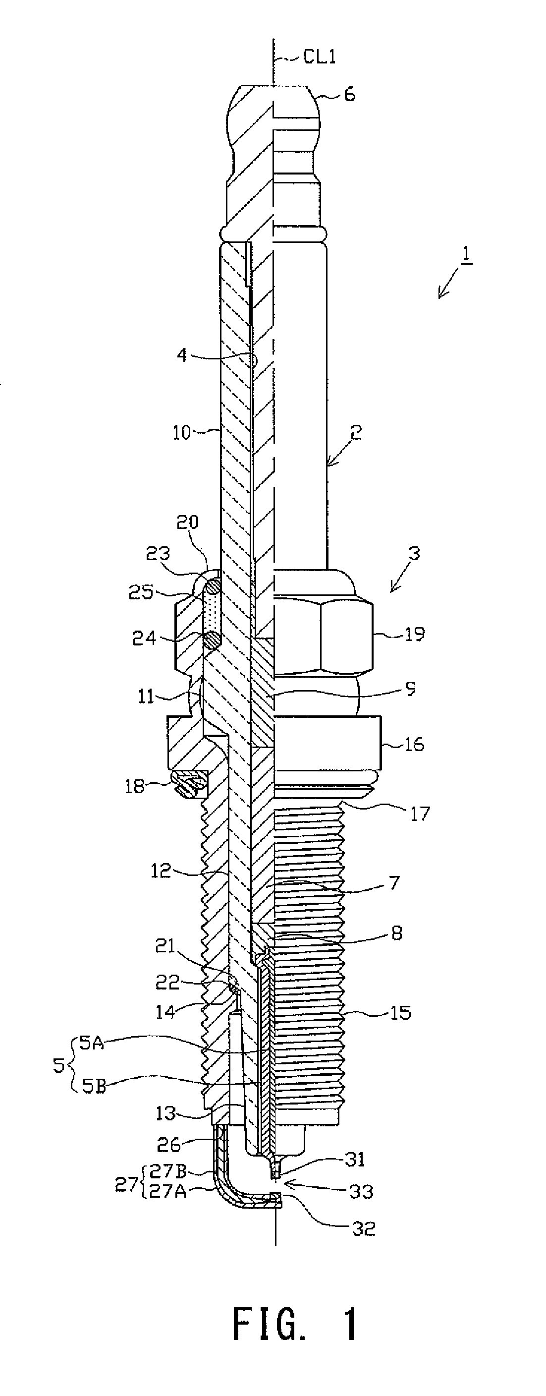
[0050]One embodiment will next be described with reference to the drawings. FIG. 1 is a partially sectioned front view showing a spark plug 1. In the following description, the direction of an axis CL1 of the spark plug 1 in FIG. 1 is referred to as the vertical direction, and the lower side of the spark plug 1 in FIG. 1 is referred to as the forward end side of the spark plug 1, and the upper side as the rear end side of the spark plug 1.

[0051]The spark plug 1 is composed of a tubular ceramic insulator 2, a tubular metallic shell 3 which holds the ceramic insulator 2, etc.

[0052]The ceramic insulator 2 is formed from alumina or the like by firing, as well known in the art. The ceramic insulator 2 includes a rear trunk portion 10, a large-diameter portion 11, an intermediate trunk portion 12, and a leg portion 13, which form the external shape of the ceramic insulator 2. The rear trunk portion 10 is formed on the rear end side. The large-diameter portion 11 is located forward of the ...


PUM


Abstract

A spark plug including a ceramic insulator having an axial hole, a center electrode inserted into the axial hole, a metallic shell provided around the insulator, a ground electrode fixed to the metallic shell, and a tip joined to a distal end portion of the ground electrode and forming a spark discharge gap between the tip and a forward end portion of the center electrode. The ground electrode includes an outer layer and an inner layer provided inside the outer layer and formed of a metal containing copper as a main component. The tip is joined to the ground electrode by a fusion portion containing a metal forming the tip and a metal forming the outer layer. The fusion portion is in contact with the inner layer and contains copper. The spark plug efficiently conducts heat from the tip to the inner layer to improve corrosion resistance of the tip.

Description

FIELD OF THE INVENTION[0001]The present invention relates to a spark plug used for an internal combustion engine or the like.BACKGROUND OF THE INVENTION[0002]A spark plug used for a combustion apparatus such as an internal combustion engine includes, for example, a center electrode extending in an axial direction, an insulator provided around the center electrode, a tubular metallic shell provided around the insulator, and a ground electrode whose proximal end portion is joined to a forward end portion of the metallic shell. The ground electrode is bent at its intermediate portion such that its distal end portion faces the center electrode, whereby a spark discharge gap is formed between a forward end portion of the center electrode and the distal end portion of the ground electrode.[0003]Also, there has been known a technique of providing a tip formed of a noble metal alloy or the like on a portion of the ground electrode, which portion forms the spark discharge gap, to thereby imp...

Claims


Application Information

Patent Timeline
Patent Type & Authority Patents(United States)
IPC IPC(8): H01T13/20H01T13/32
CPCF02P13/00H01T13/32H01T13/16H01T13/39H01T13/20
Inventor KATAOKA, YOSHIKAZU
Owner NGK SPARK PLUG CO LTD
Why Eureka
Try Eureka