
Filling process for dual fluid cartridge assemblies

Active Publication Date: 2005-02-01
NORDSON CORP
View PDF5 Cites 38 Cited by
  • Summary
  • Abstract
  • Description
  • Claims
  • Application Information

AI Technical Summary

Benefits of technology

A problem exists with filling such cartridges. In particular, it is normally necessary to bleed air from the cartridge to prevent air from being trapped within the cartridge during filling. Such trapped air is known to have a negative impact on the ability to control the volumetric ratio of the fluids dispensed. If air is trapped in the inner cartridge, for example, the initial movement of the piston seals and accompanying increase in pressure in the cartridge chamber will act will cause that air to be compressed rather than to force fluid out of the outlet of the cartridge. Therefore, as the pressure in the cartridge increases during the early phase of the dispensing cycle, a smaller amount of the fluid in the inner cartridge will be dispensed than is desired. As the pressure in the cartridge decreases later, the air still trapped in the inner cartridge will expand and cause a larger than desired amount of fluid to be dispensed from the inner cartridge during the later phase of the dispensing cycle. If a different amount of air is trapped in the outer cartridge, the air will compress and expand at different rates than that of the air in the inner cartridge chamber. The difference in these rates will cause variation in the ratio of the fluids dispensed from the two cartridge chambers. This variation may have a negative impact on the performance of the fluids to be mixed.

Problems solved by technology

A problem exists with filling such cartridges.
Such trapped air is known to have a negative impact on the ability to control the volumetric ratio of the fluids dispensed.
This variation may have a negative impact on the performance of the fluids to be mixed.
Unfortunately, there are several problems associated with this method.
First, the shims can become fouled by way of contact with a fluid, thus eliminating or reducing the effectiveness of the shims.
Second, the shims and wires are prone to breaking and curling due to their relatively small cross sections.
Third, such shims and wires must be replaced periodically.
Fourth, burrs and sharp edges along the length of the shims are known to damage the piston seal and thus affect its performance.
Lastly, the use of wires or shims requires extra steps and thus increases the cost of filling the cartridge assembly.
Unfortunately, since it takes time to draw a vacuum, this approach increases the time required to fill the cartridge.
Unfortunately, such systems require additional steps and components and thus increase the time and cost of filling such cartridges.

Method used


Image

  • Filling process for dual fluid cartridge assemblies
  • Filling process for dual fluid cartridge assemblies
  • Filling process for dual fluid cartridge assemblies

Examples


Embodiment Construction

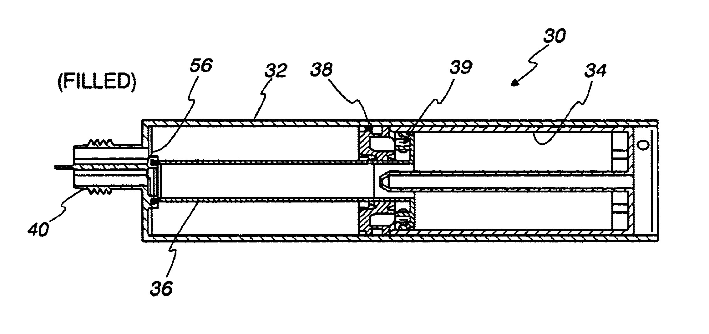
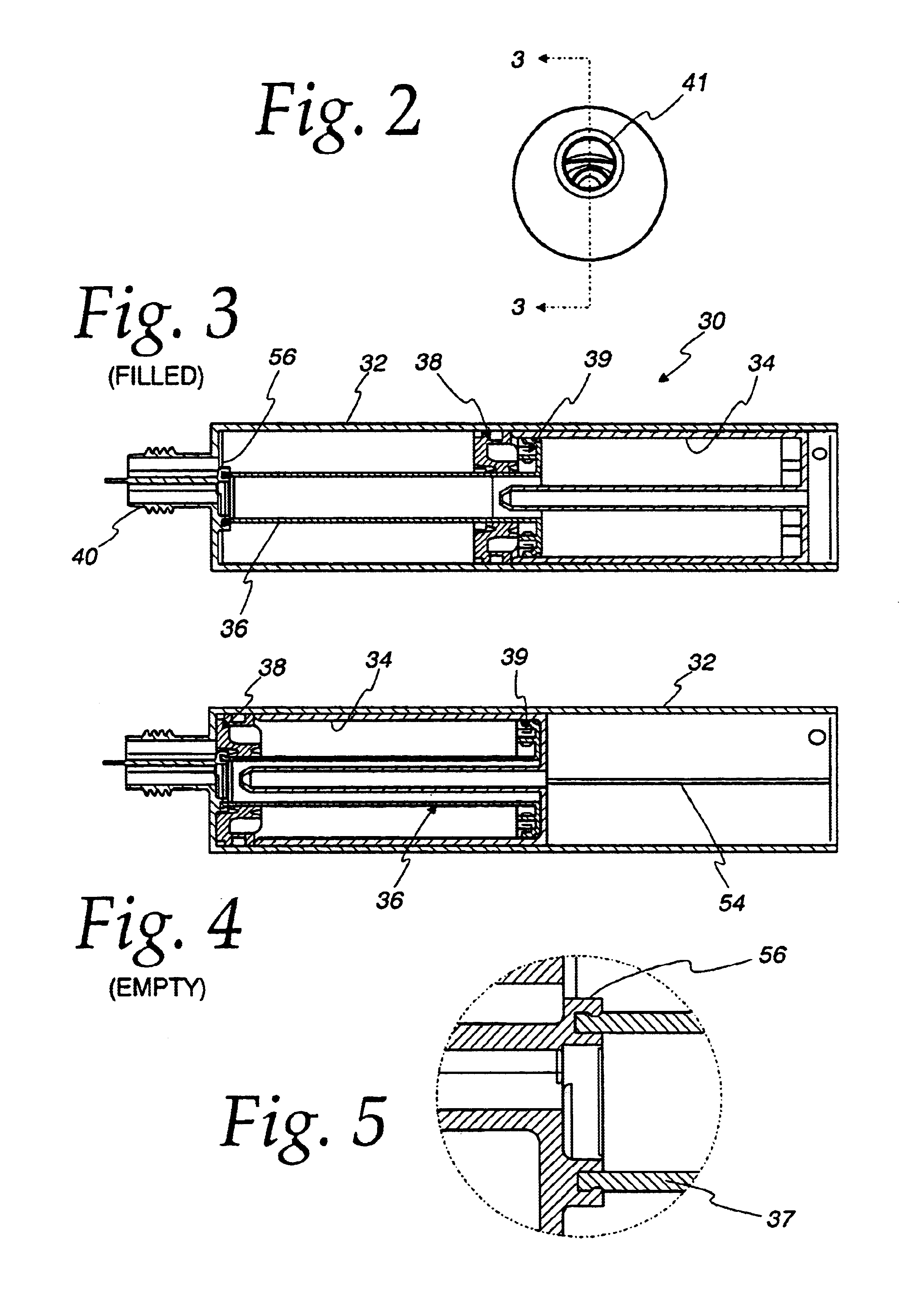
The present invention relates to a method for filling a dual fluid cartridge assembly which automatically fills and bleeds the cartridge assembly prior to filling without additional steps and without a vacuum. Unlike other known methods for filling dual fluid cartridge assemblies, the method in accordance with the present invention utilizes an automatic filling machine in conjunction with a self-bleeding dual fluid cartridge assembly that is configured with a vent to atmosphere which allows air in the inner cartridge to be automatically evacuated during the fill process in order to prevent any trapped air pockets within the fluid in the inner cartridge. A vent may also be optionally provided in order to vent trapped air from the chamber formed by the outer cartridge as well.

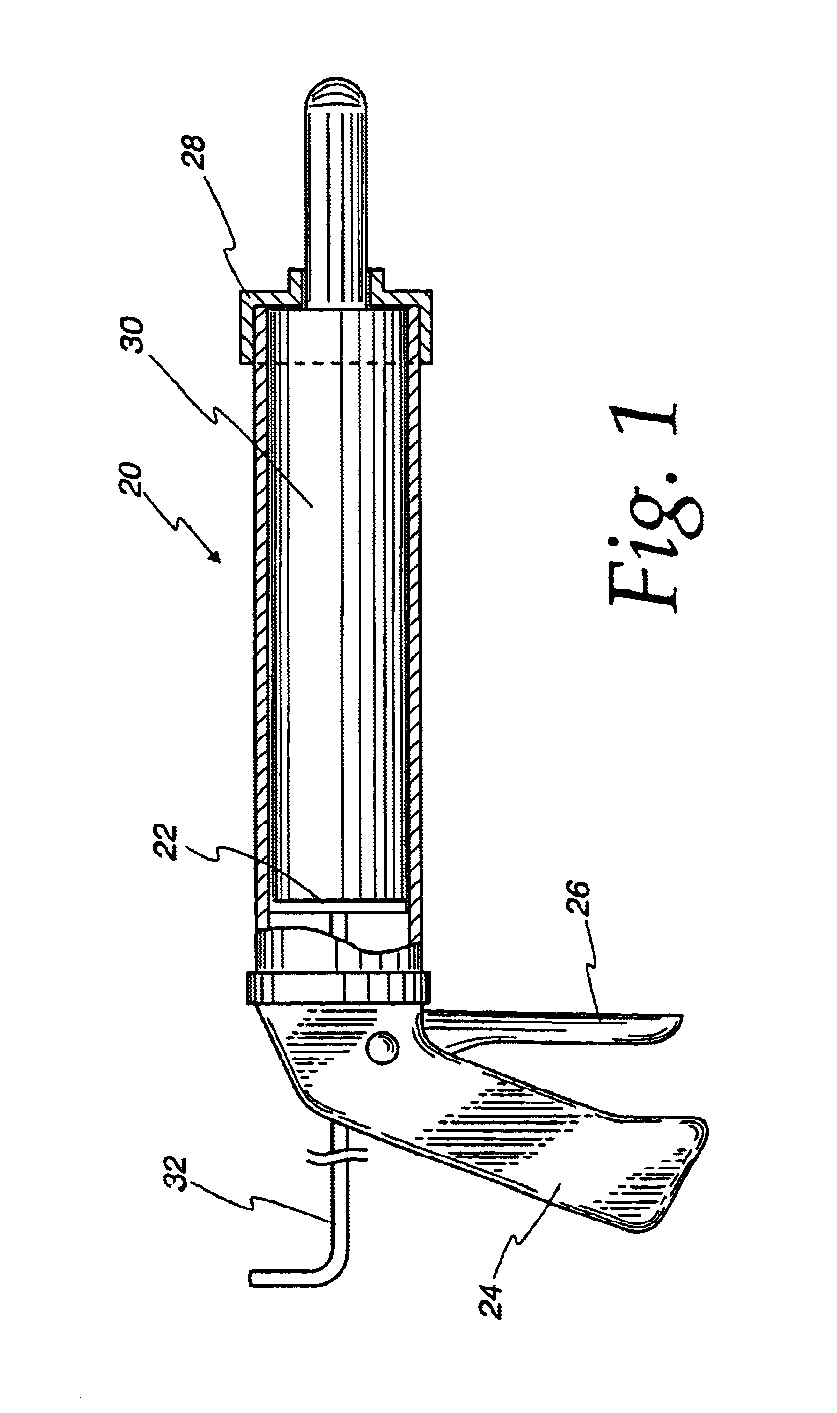
The method in accordance with the present invention is adapted to be utilized with a dual fluid cartridge assembly as illustrated in FIGS. 2-20 and described below. An exemplary filling machine for automatically ...


PUM

PropertyMeasurementUnit
Timeaaaaaaaaaa

Abstract

A method for filling a dual fluid cartridge assembly which automatically bleeds air from the cartridge to filling and without extra steps or a vacuum as in known filling methods. In particular, the process relates to providing a dual fluid cartridge assembly which includes vents that bleed air from the cartridges initially and automatically closes the vents as the piston seal moves away from the vent. By utilizing such a self-bleeding cartridge assembly, the cartridge can be filled by a fluid dispenser without the need for shims, a vacuum or bleed plugs.

Description

BACKGROUND OF THE INVENTION1. Technical FieldThe present invention relates to a filling process and more particularly to a filling process for automatically filling dual fluid cartridge assemblies.2. Description of the Prior ArtFluid cartridge assemblies are generally known in the art. Both single and multiple fluid cartridge assemblies are known. An example of a single fluid cartridge assembly is disclosed in commonly owned international patent application number PCT / US02 / 39041, filed on Dec. 6, 2002. Such a fluid cartridge assembly is used to dispense a single fluid.Dual fluid cartridge assemblies are also known. Examples of such dual fluid cartridge assemblies are disclosed in U.S. Pat. Nos. 4,220,261; 4,961,520; and 5,310,091. Such dual fluid cartridge assemblies are known to be used to dispense fluid materials, such as thermoset adhesives, which typically contain two fluids that need to remain separated and applied to a workpiece quickly after mixing.U.S. Pat. No. 5,310,091 dis...

Claims


Application Information

Patent Timeline
IPC IPC(8): B65B3/10B65D81/32B65B3/12B67D7/70
CPCB05C17/00553B05C17/00559B65B3/12B65D81/325B05C17/01B65D2205/04
Inventor BRENNAN, ROBERT CHARLES
Owner NORDSON CORP
Learn More