
Condensing cycle with energy recovery augmentation

a technology of energy recovery and condensing cycle, which is applied in the direction of domestic cooling apparatus, energy-efficient board measures, lighting and heating apparatus, etc., can solve the problems of inefficient operation, inconvenient operation, and the operation of the first turbine would waste energy, so as to save even more aircraft space and fuel

Inactive Publication Date: 2005-02-01
HONEYWELL INT INC
View PDF11 Cites 38 Cited by
  • Summary
  • Abstract
  • Description
  • Claims
  • Application Information

AI Technical Summary

Benefits of technology

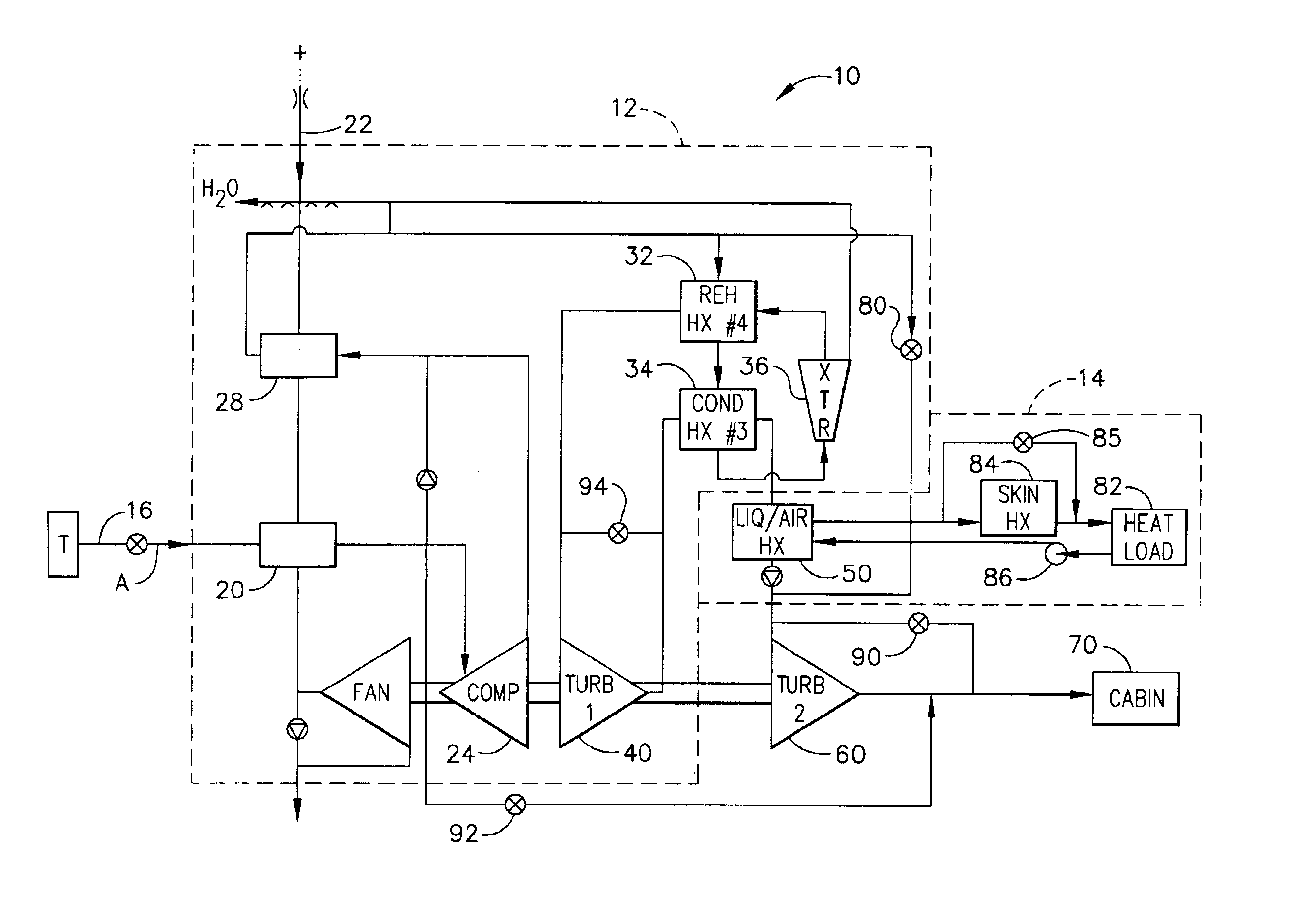
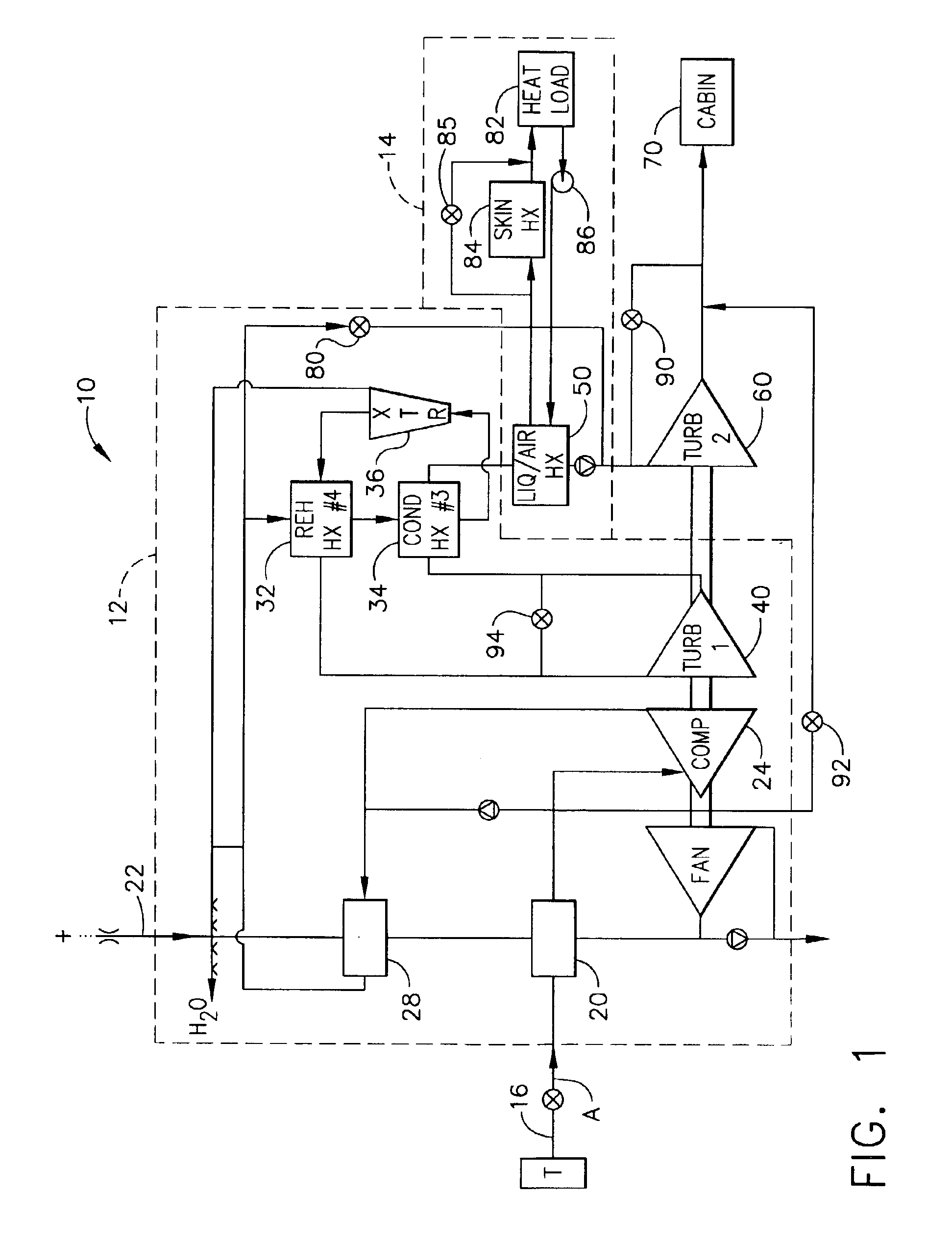
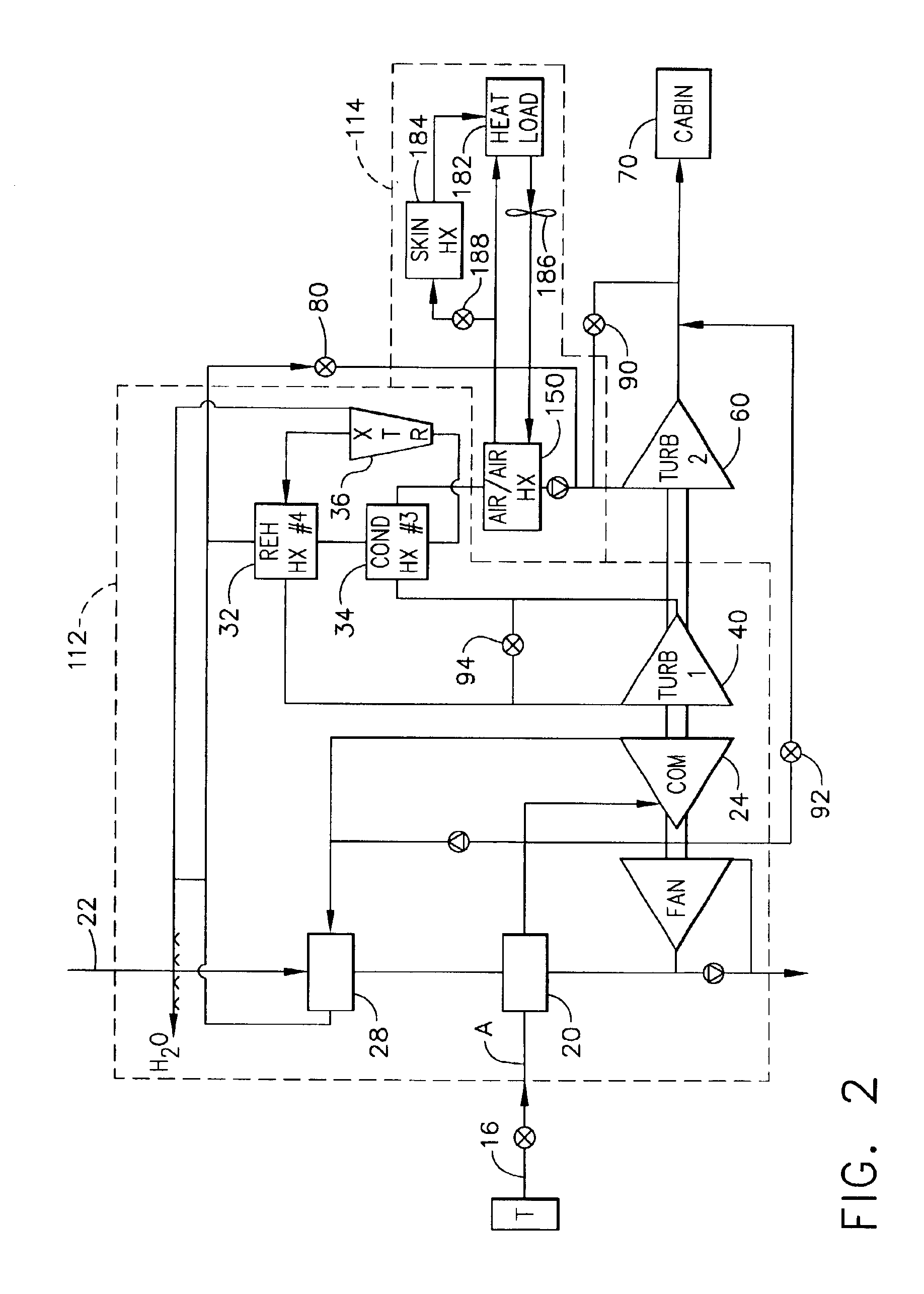
In a still further aspect of the invention, a method of providing conditioned air for an aircraft cabin is described. The method includes the steps of bleeding inlet air from an aircraft turbine engine, then cooling it, dehumidifying it and compressing it in an air sub-cycle that can recapture at least a portion of the heat of vaporization of the condensed moisture. The method also includes heating inlet air with a third heat exchanger using waste heat from the aircraft. The method includes expanding the inlet air in a second turbine. The method also includes a step of bypassing the first turbine when the aircraft is in ambient air that is cooler and dryer then the condition desired in the cabin. This step saves bleed air that would otherwise be unnecessarily bled from the aircraft engine by the first turbine. The efficiency of this arrangement allows system components to be smaller which saves even more aircraft space and fuel.

Problems solved by technology

However, '097 does not disclose a way to continue to cool the aircraft avionics when the avionics heat energy is not needed in the air cycle.
Aircraft electronics and avionics must be cooled constantly or they will overheat.
For example, during high altitude performance, when ambient air is cooler and bleed air is less humid than at ground level, operation of the first turbine would waste energy by drawing un-needed bleed air from the turbine engine.
The inefficient operation of Warner forces designers to build the system components, particularly heat exchangers, larger than needed which in turn wastes more aircraft fuel in carrying the additional weight.

Method used


Image

  • Condensing cycle with energy recovery augmentation
  • Condensing cycle with energy recovery augmentation
  • Condensing cycle with energy recovery augmentation

Examples


Embodiment Construction

The following detailed description is of the best currently contemplated modes of carrying out the invention. The description is not to be taken in a limiting sense, but is made merely for the purpose of illustrating the general principles of the invention, since the scope of the invention is best defined by the appended claims.

It is necessary to cool and condition air for supply to a cabin space of an aircraft. The system used must perform in a variety of conditions including in relatively warm moist air when the aircraft is on the ground and inlet air comes from an auxiliary power source, and in cool dry air when the aircraft is at high altitude. In flight it is common practice to use air bled from a turbine engine as inlet air and to condition the inlet air to cool and dehumidify the air. The disclosed invention conditions inlet air using an efficient process that recaptures energy that would otherwise be wasted. Recaptured energy can come from aircraft avionics and from moisture...


PUM


Abstract

A system and method for providing conditioned air to an aircraft cabin. The system combines the benefits of a traditional 4 wheel condensing cycle and dual expansion energy recovery cycles. The energy of a heat load such as aircraft electronic or avionics can be recovered and used in a second turbine while a continuous source of cooling for the heat load is provided for high altitude operation when the first turbine is by-passed. The disclosed invention conditions inlet air using an efficient process that recaptures energy that would otherwise be wasted. Recaptured energy can come from aircraft avionics and from moisture in inlet and cabin air.

Description

BACKGROUND OF THE INVENTIONThe present invention relates generally to apparatus and methods for conditioning inlet air for use in an aircraft cabin and, more particularly to apparatus and methods for conditioning cabin air while capturing and reusing energy that would otherwise be waste.In aircraft operating in atmospheres with low pressure it is necessary to condition the cabin air to increase pressure and provide temperature and humidity control.U.S. Pat. No. 6,250,097 shows a combined 4 wheel air cycle and liquid cycle system used to cool aircraft cabin air and avionics while recovering some heat energy in the process. In '097, an air cycle includes, inlet air from an aircraft turbine cooled by ambient air, compressed and cooled again by ambient air. The inlet air is then cooled again by use of reheat heat exchangers which route the warm moist inlet air over cooled inlet air downstream in the system. The inlet air is then expanded through a first turbine and water is extracted. T...

Claims


Application Information

Patent Timeline
IPC IPC(8): B64D13/06B64D13/00
CPCB64D13/06Y02T50/56B64D2013/0648Y02T50/50
Inventor CLAEYS, HENRY M.
Owner HONEYWELL INT INC
Learn More