
Method and apparatus for acoustic suppression of cavitation

a cavitation and acoustic technology, applied in the field of acoustic cavitation, can solve the problems of affecting the cavitation effect,

Inactive Publication Date: 2005-01-25
OVIVO SWITZERLAND AG
View PDF7 Cites 2 Cited by
  • Summary
  • Abstract
  • Description
  • Claims
  • Application Information

AI Technical Summary

Benefits of technology

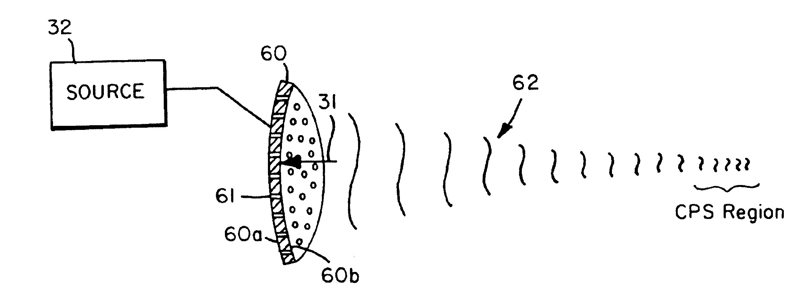
According to a first aspect of the present invention, a method of suppressing cavitation in or about a region of a surface that is subjected to cavitation-producing energy comprises providing a transducer and exciting the transducer to produce a biased acoustic field comprising a series of pressure pulses in the region that exceed peak negative tensile force of cavitation-producing energy.

Problems solved by technology

Cavitation concentrates energy; its occurrence may deleteriously erode surfaces of mechanical elements, even elements made of tungsten or steel.
Problematic cavitation is encountered in land, sea, and air vehicles or equipment, whose designs are typically made to avoid cavitation events.
But even today suppressing cavitation has not successfully been achieved; it still remains an engineering priority.
Developing cavitation-proof structural designs and materials often leads to extremely conservative designs, invariably underrealizing the full performance potential of many systems.
Cavitation also limits the amount of power that may be mechanically coupled to fluids in hydraulic systems.
It is extremely difficult, however, to create cavitation in fully wetted regions associated with liquids because homogeneous nucleation thresholds generally exceed several hundred atmospheres of peak negative pressure.
If, however, overpressuring does not fully wet all cavitation nuclei, should cavitation occur, the violence of cavitation implosion in the statically overpressured environment would be more energetic thereby causing greater surface damage, thus defeating the purpose of cavitation-proof design in the first place.
Such physical containment constitutes a primary limitation to cavitation suppression on exterior surfaces of a mechanical element or structure, like a sonar dome or propeller of a sea vessel.

Method used


Image

  • Method and apparatus for acoustic suppression of cavitation
  • Method and apparatus for acoustic suppression of cavitation
  • Method and apparatus for acoustic suppression of cavitation

Examples


Embodiment Construction

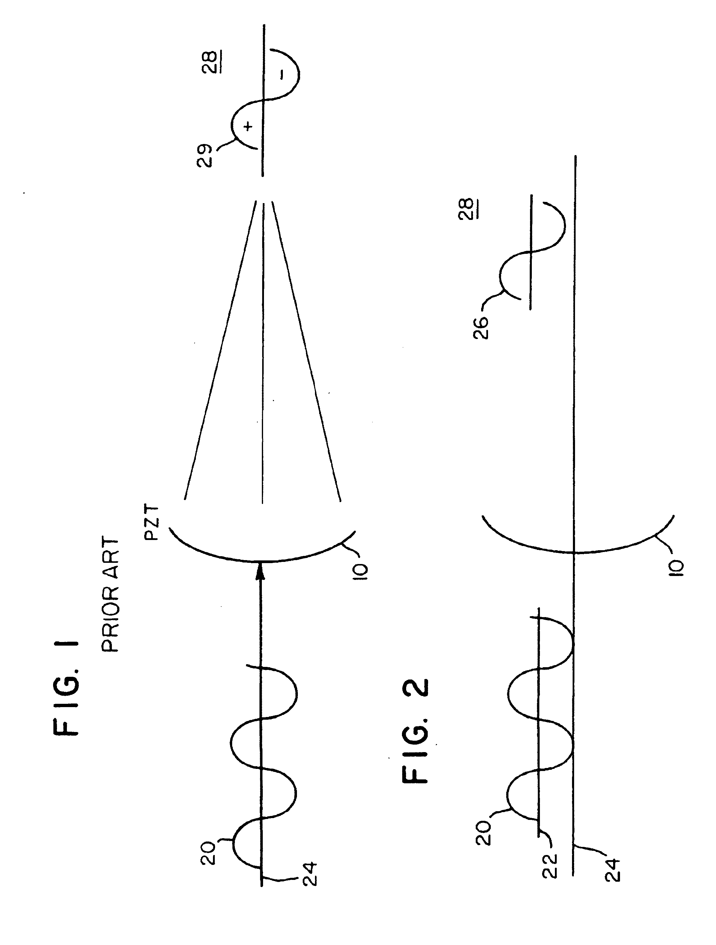
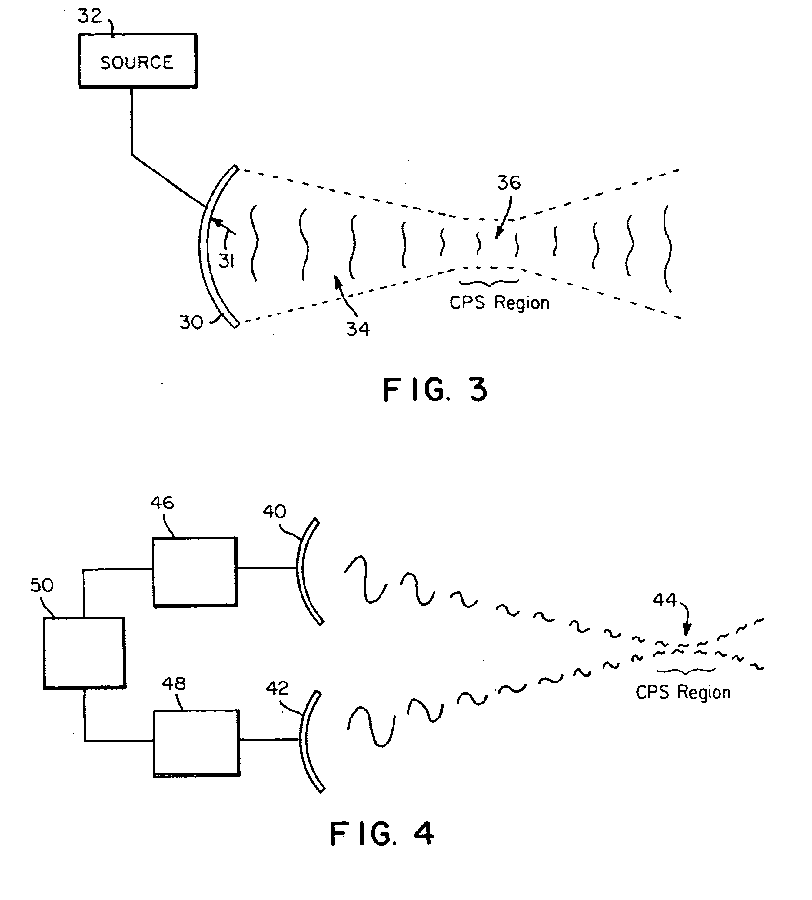
According to an aspect of the present invention, cavitation prevention is achieved by suppressing the rarefaction or tensile phase of insonifying waves, i.e., by ensuring that the acoustic waves only contain compressive peaks in rapid succession. Ordinarily, AC power amplifiers that drive the transducer amplify the driving voltage symmetrically about a ground reference level even when the inputs contain a DC bias. However, by introducing an appropriate biasing circuit between the output of the power amplifiers and the input of the acoustic wave producer, e.g., a transducer, it may be possible to produce an acoustic field that yields only positive pressure pulses or positive wave halves.

Driving a transducer so that high frequency, high amplitude sequences of positive pressure pulses present over the CPS of a targeted region effectively provides a “containerless” hyperbaric environment and precludes cavitation events. Various methods and apparatuses may be employed to provide such bia...


PUM


Abstract

The invention provides a method and apparatus for suppressing hydrodynamic cavitation through the use of high frequency (>500 kHz) and high amplitude (>1 atmospheres) acoustic energy. The method includes biasing a transducer driving signal to generate an acoustic field having a positive pressure halves. The resulting acoustic field is imposed on a region where cavitation is to be preempted. A cavitation preempting acoustic field in the liquid is similar in effect as using a hyperbaric confinement for imposing hydrostatic pressure, a known method for suppressing cavitation. In this regime, suppression of cavitation will be due to imposing a dominant high amplitude, high-frequency pressure field to ensure that the gaps between the compressive pulses are shorter than 10−7 to 10−6 seconds, which is less than that typically necessary to cause cavitation.

Description

BACKGROUNDThe invention concerns acoustic cavitation, but more specifically, the invention concerns a method of and an apparatus for suppressing cavitation on a surface of an element in a mechanical system, such as working surfaces in hydraulic equipment.Cavitation concentrates energy; its occurrence may deleteriously erode surfaces of mechanical elements, even elements made of tungsten or steel. Problematic cavitation is encountered in land, sea, and air vehicles or equipment, whose designs are typically made to avoid cavitation events. At least one hundred years have passed since initial studies of propeller erosion, and since then, much knowledge has been gained in the industry about bubble dynamics and the energetics of cavitation. But even today suppressing cavitation has not successfully been achieved; it still remains an engineering priority. Developing cavitation-proof structural designs and materials often leads to extremely conservative designs, invariably underrealizing t...

Claims


Application Information

Patent Timeline
Patent Type & Authority Patents(United States)
IPC IPC(8): F04D29/66G10K15/02G10K11/16G10K11/00B63H1/18B63H1/00
CPCG10K15/02G10K11/16F04D29/669B63H1/18Y10T137/0391Y10T137/0396Y10T137/2196
Inventor MADANSHETTY, SAMEER I.
Owner OVIVO SWITZERLAND AG
Learn More