
Low torque seal assembly

a low-torque, sealing technology, applied in the direction of mechanical equipment, machines/engines, transportation and packaging, etc., can solve the problems of seal wear, power loss, and bearing assembly operation in hostile environments, and achieve the effect of less torque to rotate and reducing power loss in the rotating system

Inactive Publication Date: 2005-01-25
STEMCO LP
View PDF32 Cites 36 Cited by
  • Summary
  • Abstract
  • Description
  • Claims
  • Application Information

AI Technical Summary

Benefits of technology

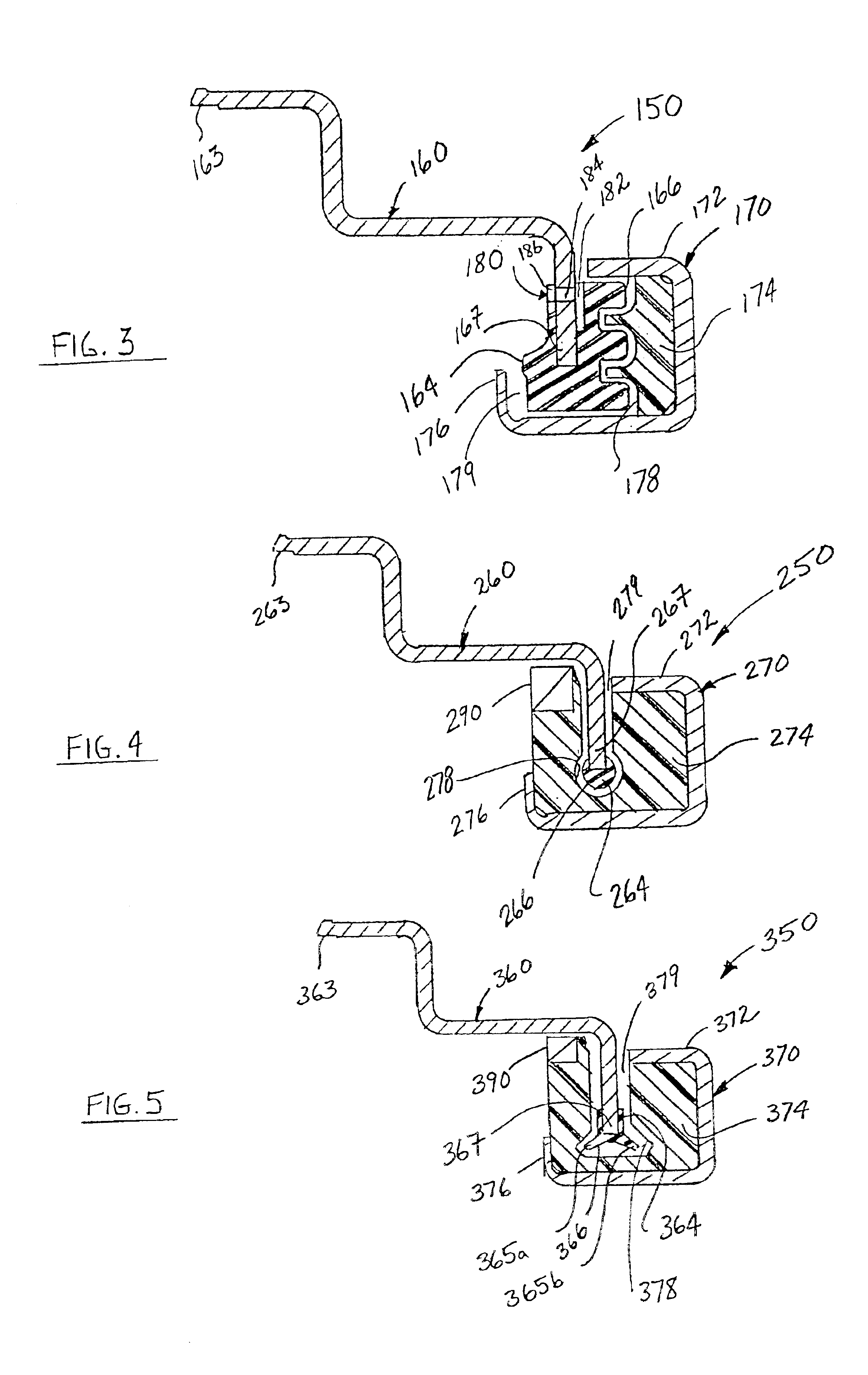
The inner cylinder is coaxially positioned within the outer cylinder and defines a second race surface on its outer diameter. A bearing chamber is defined between the outer cylinder and the inner cylinder. The plurality of bearings are disposed within the bearing chamber and are in rolling contact with the first and the second race surfaces. Each bearing facilitates the rotational movement of the inner cylinder with respect to the outer cylinder or vise versa. The outer ring includes a casing which has an axially inner and an axially outer end and a first shield element. The first shield element is engaged with the outer end of the casing and defines a first sealing face.
Those skilled in the art will readily appreciate that the unitized seal assembly of the subject disclosure excludes contaminants from within the bearing chamber and prevents lubricant from escaping therefrom while requiring less torque to rotate, thereby reducing power losses in the rotating system. These and other unique features of the unitized seal assembly disclosed herein will become more readily apparent from the following description, the accompanying drawings and the appended claims.

Problems solved by technology

Bearing assemblies often operate in hostile environments, and this is particularly true when they are used in application such as railcars.
Although contacting lip seals adequately perform the sealing function, the contact between the lip and the sealing surface causes seal wear and a loss of power in the rotating system due to friction between the two surfaces.
In addition to the interference between the lip and the sealing surface, the elasticity of the rubber element and the spring force (if used) applied thereto creates a radial load which results in additional torque requirements.

Method used


Image

  • Low torque seal assembly
  • Low torque seal assembly
  • Low torque seal assembly

Examples


Embodiment Construction

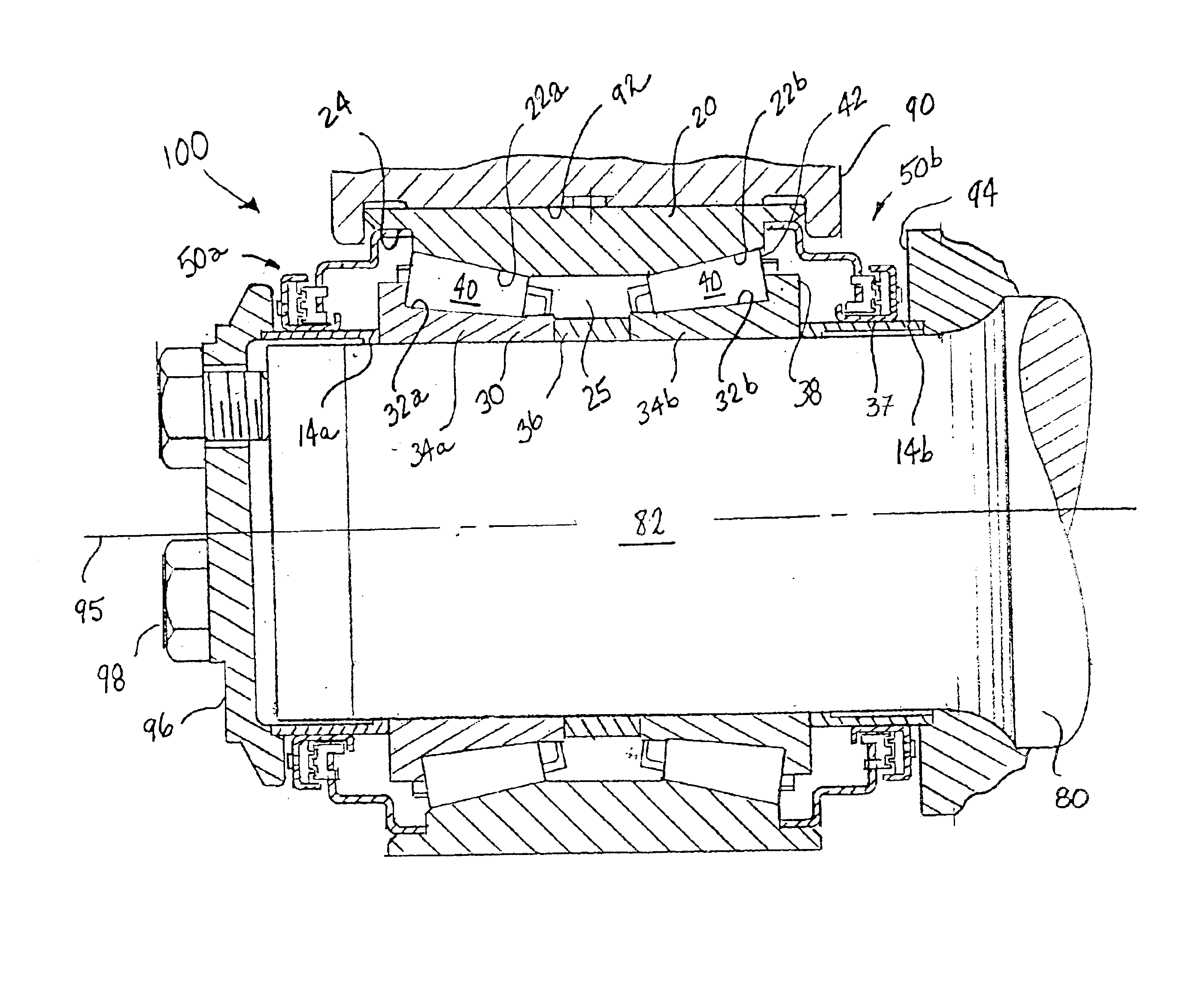
Referring now to the drawings wherein like reference numerals identify similar elements of the subject invention, there is illustrated in FIG. 1 a unitized bearing seal assembly constructed in accordance with a preferred embodiment of the subject disclosure and designated generally by reference numeral 100. Bearing seal assembly 100 includes bearing component 10 and axially opposed first and second interlocking seal assemblies 50a and 50b.

Bearing component 10 is a two row tapered roller bearing which includes an outer ring or double cup 20, an inner ring 30, and a plurality of circumferencially-spaced apart tapered rollers 40 disposed within an interior chamber 25 defined between the cup 20 and the inner ring 30. Angled surfaces 22a and 22b are formed on the interior portion of cup 20 and are oriented so as to correspond with the taper angle of rollers 40. Similarly, inner ring 30 includes angled surfaces 32a and 32b which are also oriented so as to correspond to the taper angle of...


PUM


Abstract

A unitized seal assembly for use with roller or ball bearing assemblies is disclosed. The unitized seal assembly includes, among other things, a radially outer ring and a radially inner deflector ring. The outer ring includes a first shield element which defines a first sealing face. The radially inner deflector ring includes a second shield element which defines a second sealing face. The second sealing face is dimensioned and configured so as to correspond to the first sealing face such that when the first shield element is positioned in non-contacting proximity to the second shield element, a circuitous sealing labyrinth is formed between the first sealing face and the second sealing face.

Description

BACKGROUND OF THE INVENTION1. Field of the InventionThe subject disclosure relates to unitized bearing seal assemblies, and more particularly to, a low torque seal assembly which utilizes a highly viscous fluid filled labyrinth path to maintain a seal and exclude contaminants from within an interior bearing chamber.2. Background of the Related ArtBall and roller bearing assemblies are well known in the art and have been used for many years in applications such as railway cars, crane wheels, and trucking. Bearing assemblies are typically provided as a self-contained unit and generally include a plurality of circumferentially-spaced balls or rollers confined between concentric outer and inner rings or cylinders. The concentric rings define an interior chamber for containing the rolling elements and supply smooth, hard, accurate surfaces for the balls or rollers to roll on. These surfaces are referred to as races or raceways. A uniform spacing is maintained between adjacent balls or ro...

Claims


Application Information

Patent Timeline
IPC IPC(8): F16C33/04F16C33/10F16C33/78F16C33/80F16C33/76F16J15/447F16J15/40F16J15/44F16J15/43F16J15/32
CPCF16C33/765F16C33/7813F16J15/4478F16J15/3244F16J15/3256F16C33/80F16C2326/10F16C19/386F16C2326/02
Inventor HOOD, CHARLES ROBINWELLS, DONALD G.GOLD, MARK N.
Owner STEMCO LP
Learn More