Eureka AIR delivers breakthrough ideas for toughest innovation challenges, trusted by R&D personnel around the world.

Shaping shoulder and a device for producing longitudinally shaped webs

Inactive Publication Date: 2005-01-25
GVL FUR VERPACKUNGSTECHN UND LOGISTIK MBH
View PDF16 Cites 59 Cited by
  • Summary
  • Abstract
  • Description
  • Claims
  • Application Information

AI Technical Summary

Benefits of technology

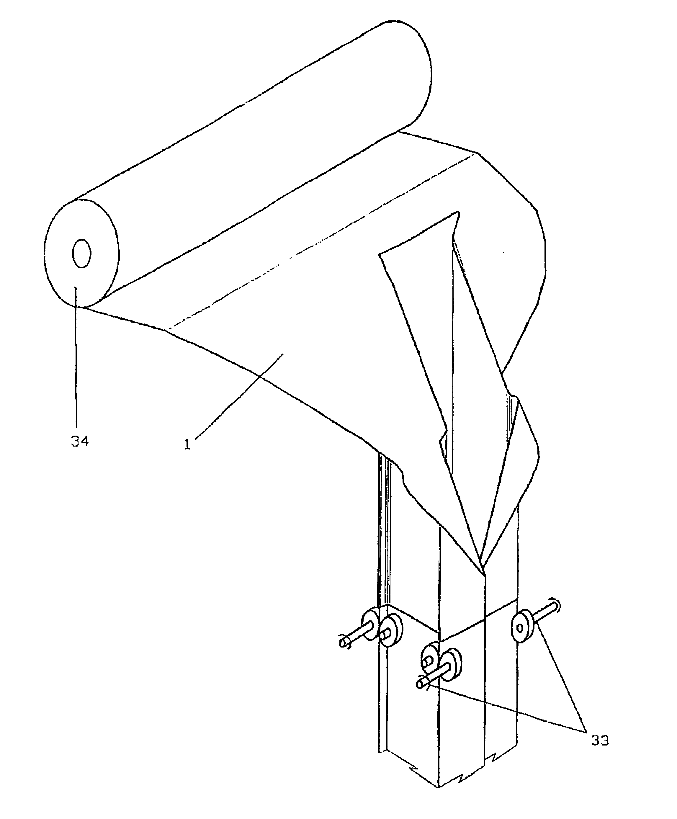
Surprisingly, it was found that shaping processes which have been very complex in the past can be realized by means of the shaping shoulder according to the invention. In this way, the manufacture of the bags with folds but also of tubular film bags which are divided several times in the longitudinal direction is possible.
In tubular film bag machines for producing tube cross-sections with stabilizing folds a significant reduction of the total shaping height in comparison to the prior art is possible. In this way, the product drop height and machine size are reduced. Additional shaping elements for forming the folds are no longer needed.
With the shaping shoulders according to the invention overlapping tube areas, for example, folds or several seam areas, are produced. The tube removal can be realized by engagement of the removal force on these overlapping areas. This is possible very simply by intermittently moving clamping grippers or by one or several roller pairs. In this way, the technical expenditure for the configuration of the tube removal is significantly reduced.

Problems solved by technology

As a result, folds and tears can form in the web or expansions can occur over portions thereof which damage the web.
A further disadvantage of this method is the long shaping path because the shaping shoulder and the fold forming members are positioned sequentially viewed in the transport direction of the tube.
This increases the machine size and the product drop height and thus causes damage of the products during the filling process.
A disadvantage of most tubular film bag machines is the technically complex tube removal.
However, it is not possible to package articles with great product height in this way.
The widening of the tube pair would constitute a non-planar shaping and would result in the above mentioned disadvantages of wrinkle formation or tear formation.
The tubes remain very flat so that they cannot be filled optimally.

Method used


Image

  • Shaping shoulder and a device for producing longitudinally shaped webs
  • Shaping shoulder and a device for producing longitudinally shaped webs
  • Shaping shoulder and a device for producing longitudinally shaped webs

Examples


Embodiment Construction

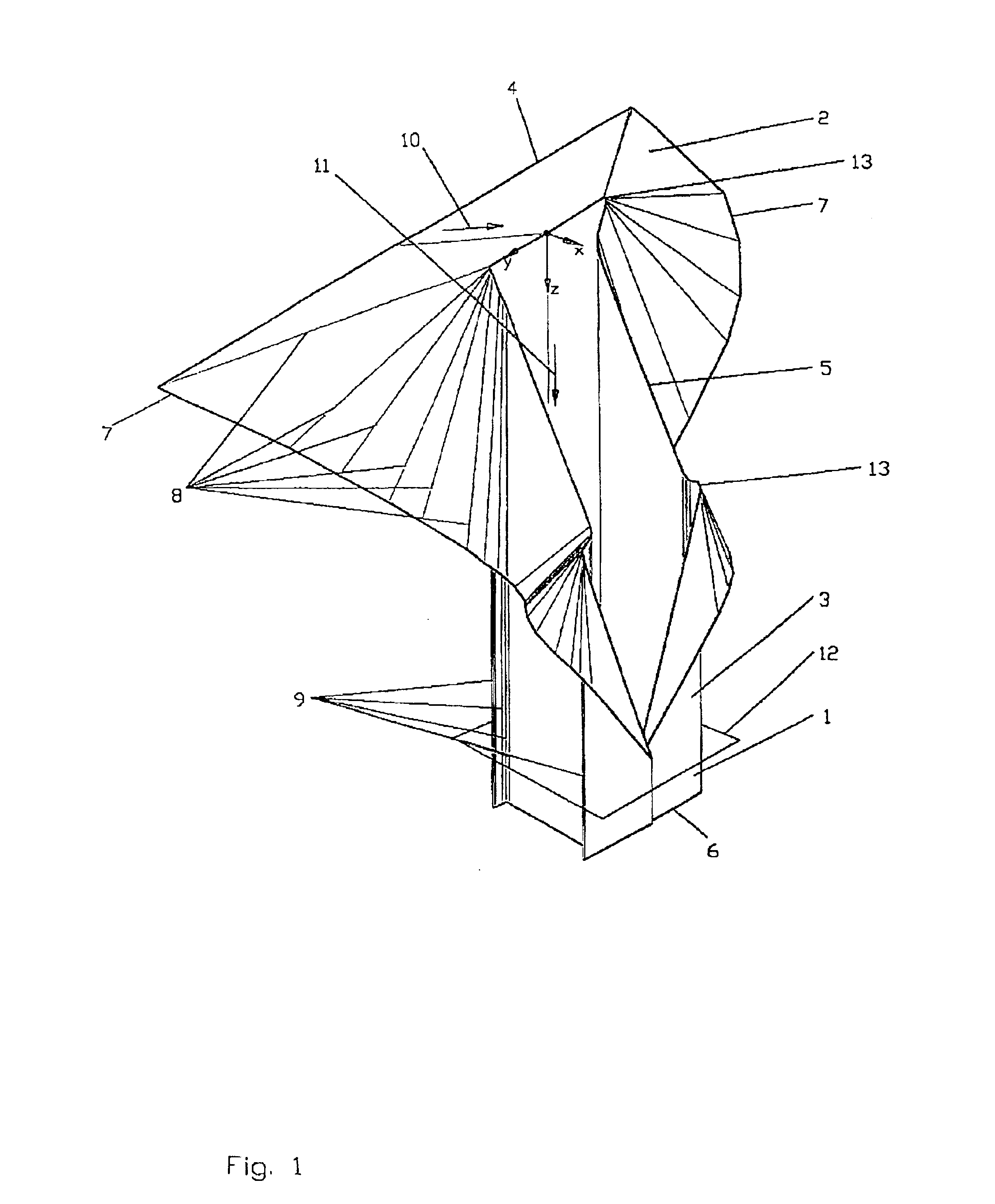
FIGS. 1 to 4 show a shaping shoulder for shaping a tube with four stabilizing folds in a perspective view (FIG. 1), in a plan view (FIG. 2), in a form developed in a plane (FIG. 3), as well as detail views of FIG. 2 and FIG. 3. The x-y-z coordinate system and the peripheral coordinate u facilitate orientation on the shaping shoulder.

The shaping shoulder (1) is comprised of a shoulder part (2) and a prism part (3). They are connected along the shaping edge (5). Viewed in the intake direction (10) of the web, the web moves from the web intake (4) on the shoulder part (2) via the shoulder part (2) to the shaping edge (5) and from there in the web transport direction (11) along the prism part (3) to the exit (6) of the tube. The web edge (7) extends along the outer boundary of the shoulder part (2).

The surface of the shoulder part (2) contacting the web is defined by straight lines, the shoulder edges (8), which extend from the shaping edge (5) to the web edge (7). The spacing between t...


PUM

PropertyMeasurementUnit
Angleaaaaaaaaaa
Speedaaaaaaaaaa
Areaaaaaaaaaaa

Abstract

A shaping shoulder has a shoulder part and a prism part, joined at a shaping edge, for producing a web, shaped longitudinally in the web transport direction and having an open or closed cross-section and at least one area inside the web in which the cross-section is curved outwardly. The shoulder part has a web inlet and extends from the web inlet to the shaping edge. The prism part has an exit for the shaped web and extends from the shaping edge to the exit. The shaping edge is slanted relative to a cross-sectional prism plane. The prism cross-section is curved partially inwardly and outwardly not only in the vicinity of a web edge. The curvature of areas of the shaping edge belonging to outwardly curved areas of the prism part extend counter to the exit and the corresponding shoulder part areas are curved away from the exit.

Description

BACKGROUND OF THE INVENTION1. Field of the InventionThe invention relates to a shaping shoulder as well as a device for producing longitudinally shaped webs having an open or closed cross-section and comprising at least one area inside the web in which the cross-section is curved outwardly. These are, for example, tubular film bags with longitudinal folds, tubular film bags with one or several chambers produced by dividing in the longitudinal direction, as well as longitudinally undulate webs.2. Discussion of the Related ArtLongitudinally shaped webs are used inter alia in the packaging technology.Generally known, employed in the packaging technology and, for example, used in horizontally or vertically operating tubular film bag machines, are shaping shoulders for shaping a plane web of a packaging material to a longitudinally shaped web, a prism which in the longitudinal direction is closed by an overlap seam or a fin seal. These closed prisms are called tubes. The removal of the p...

Claims


Application Information

Patent Timeline
IPC IPC(8): B65B9/10B65B9/22B65B9/20B65B9/207B65B9/213
CPCB29C53/52B65B9/2021B65B9/2028B65B9/213B65B9/22B65B9/207B65B2220/12
Inventor DRUT, HENRY
Owner GVL FUR VERPACKUNGSTECHN UND LOGISTIK MBH
Why Eureka
Eureka Blog
Learn More