
System and method for performance monitoring of operational equipment used with machines

a technology of performance monitoring and operational equipment, applied in the field of system and method for performance monitoring of operational equipment used with machines, can solve the problems of unfavorable lrus trending as part of the apu, difficult to track components in the field, and possible replacement of components, so as to reduce the number of delays and reduce the effect of operational cos

Inactive Publication Date: 2005-01-18
HONEYWELL INT INC
View PDF19 Cites 70 Cited by
  • Summary
  • Abstract
  • Description
  • Claims
  • Application Information

AI Technical Summary

Benefits of technology

In another aspect, the present invention may also support monitoring software that will track and compare the LRU usage and performance to determine when it has failed or is about to fail. This process is called trend monitoring. In this case it may be considered a smart trend monitoring as not only may the performance of the individual components be trended against themselves, but also they may be trended to determine how well they are operating in the system. The information may be transmitted to a collection station or stored in the system for later retrieval. Knowing how the LRU is operating compared to its as-built performance may allow the trending software to alert the operator of a pending failure prior to actual failure.
In yet another aspect, the present invention may also reduce the chance for an unscheduled replacement that may also reduce the number of delays, thus reducing operational cost. Also, the embedded chip may collect usage hours and cycle data of the LRU that may be used to schedule repairs and for warranty purposes.

Problems solved by technology

In these cases, however, the replacing of the components may occur on the tarmac adjacent the aircraft.
However, these types of components may be very difficult to track in the field.
However, trending the LRUs as part of the APU has not been very successful, as current systems do not account for or know a units current configuration.
That is they do not have a way to detect when an old LRU has been replaced with a new LRU.
Current systems fall short when an LRU may be replaced because the new LRU will affect the APU performance trend.
Currently, there is no way for the current trending systems to know that an LRU has been changed.
In addition, current systems do not use trend monitoring for the individual LRU components.

Method used


Image

  • System and method for performance monitoring of operational equipment used with machines
  • System and method for performance monitoring of operational equipment used with machines
  • System and method for performance monitoring of operational equipment used with machines

Examples


Embodiment Construction

The following detailed description is of the best currently contemplated modes of carrying out the invention. The description is not to be taken in a limiting sense, but is made merely for the purpose of illustrating the general principles of the invention, since the scope of the invention is best defined by the appended claims.

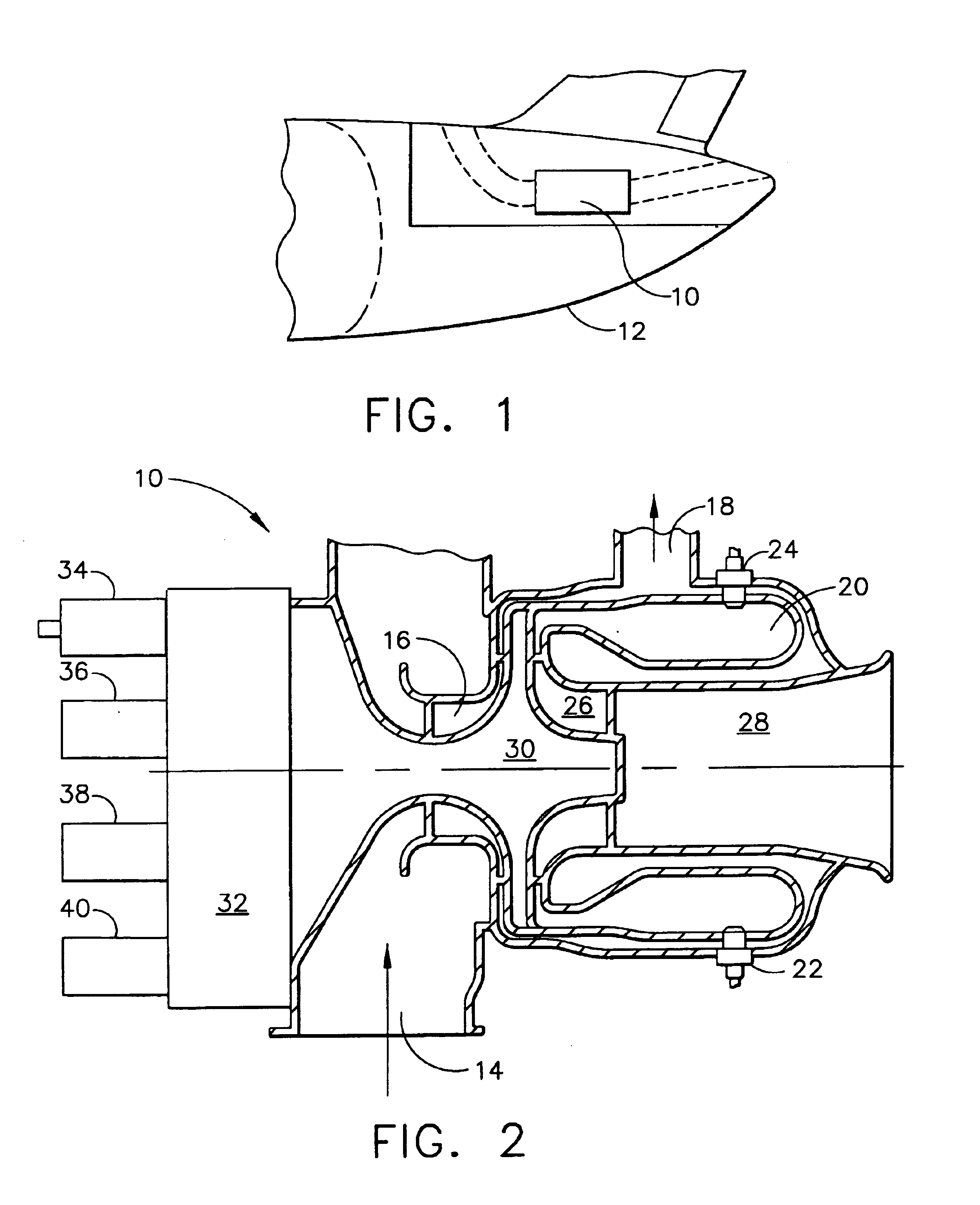
Although a large number of machines may benefit from use of the invention, for purposes of illustration, the invention may be described as it may be implemented for an APU of an aircraft as shown in FIG. 2.

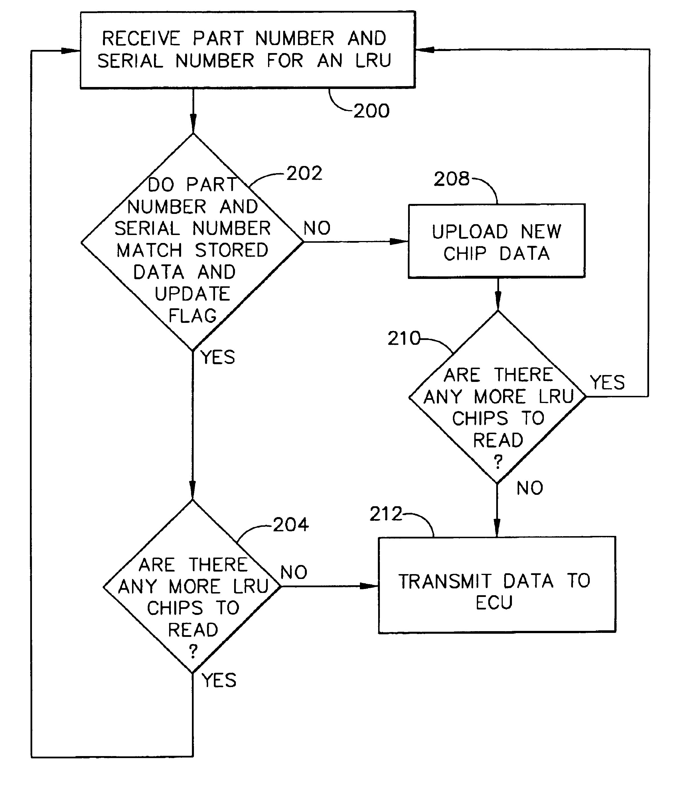
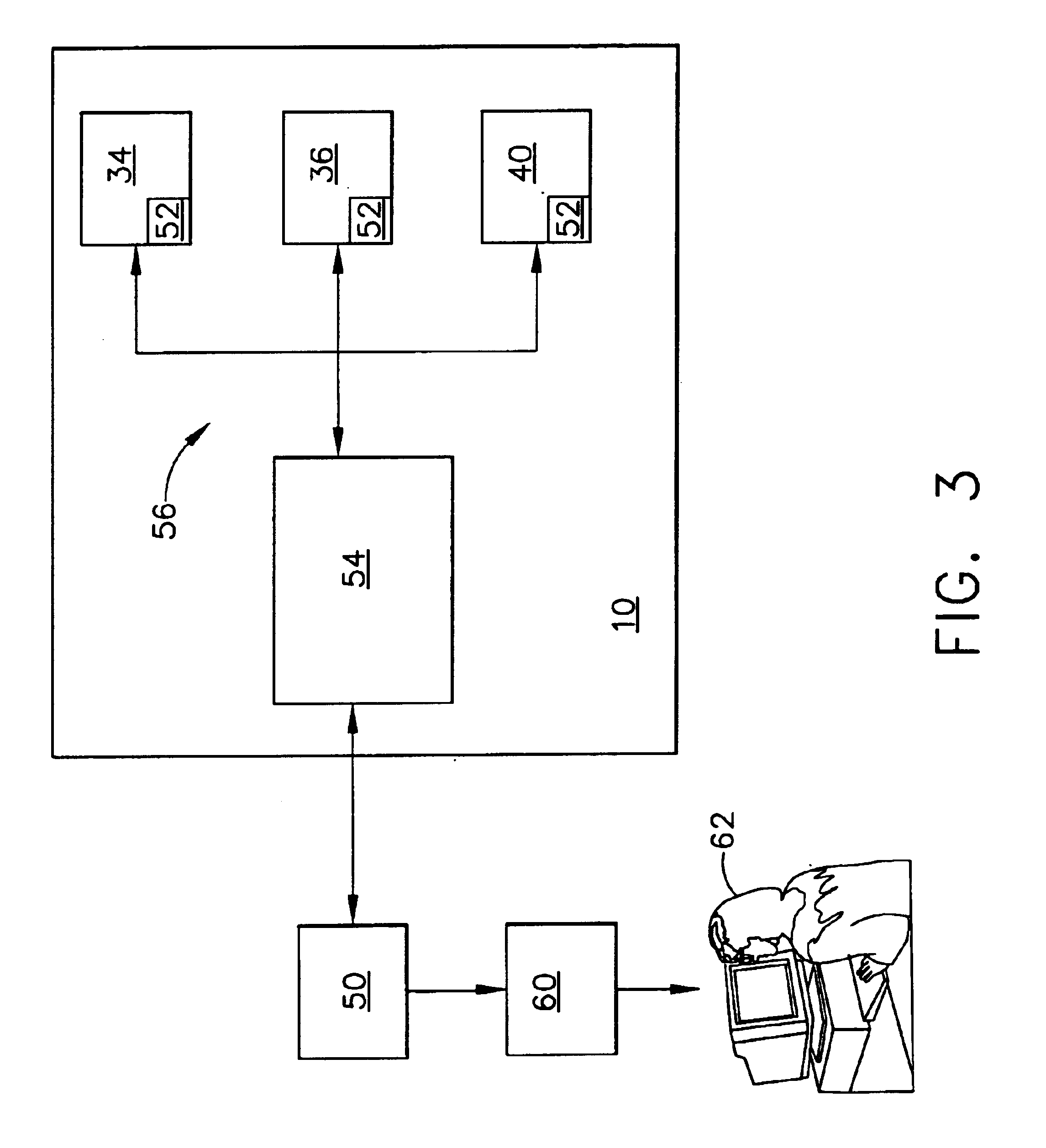
The operational sequence for monitoring the LRUs may be described in conjunction with FIGS. 2 and 3. When the operator of an aircraft wants to start the APU 10, a start command may be sent from the cockpit to the APU's electronic control unit (ECU) 50. The ECU 50 runs a diagnostics sequence checking itself and all of the LRUs 34, 36, 38, and 40 for static feedback just to assure there are no opens / shorts in the equipment. After the diagnostic check, the ECU...


PUM


Abstract

A component trend monitoring system for monitoring the performance of components and comparing the performance with stored performance data to accurately trend and predict the failure of the components. The system includes computer chips attached to the various components, for receiving and storing historical and performance data about each component, and a processor for retrieving the stored data from the memory chips. The processor receives and analyzes the data against historical data for predicting failure based upon past trends within the historical data. The processor also provides a signal for impending failure of a given component.

Description

BACKGROUND OF THE INVENTIONThe present invention relates to a method and apparatus for tracking relative to time the performance, reliability and condition of line replacement units used on aircraft and other types of machines.Auxiliary power units (APU) for aircraft may generally be gas turbine engines used on aircraft to supply pneumatic power and / or shaft horsepower when the primary propulsion engines may not be operating. Typically, as illustrated in FIG. 1, the APU 10 may be mounted in the tailcone 12 of the aircraft, though on some airplanes such as the Boeing 727, the APU may be mounted in the wheel well.Referring to FIG. 2, one form of an auxiliary power unit to which the present invention relates may generally be denoted by reference numeral 10. The APU 10 may include in flow series arrangement a compressor inlet 14, a compressor 16, a bleed port 18 for providing compressed air to the aircraft, a combustor 20 having a primary fuel nozzle 22 and a secondary fuel nozzle 24, a...

Claims


Application Information

Patent Timeline
IPC IPC(8): B64D45/00B64D41/00
CPCB64D41/00G07C5/085G07C5/008
Inventor HENRY, KENNETH W.RHODEN, JAMES A.INSKEEP, TODD MICHAEL
Owner HONEYWELL INT INC
Learn More