
Flyback converter

a converter and flyback technology, applied in the field of power conversion, can solve the problems of difficult control of switching, large load, long switching time, etc., and achieve the effect of accurate power control and simple layou

Inactive Publication Date: 2005-01-18
FAIRCHILD SEMICON CORP
View PDF1 Cites 21 Cited by
  • Summary
  • Abstract
  • Description
  • Claims
  • Application Information

AI Technical Summary

Benefits of technology

"The present invention provides a flyback converter that can detect the output voltage without using a photo coupler. This converter includes a transformer, a driving power source, a feedback unit, and a switching controller. The feedback unit detects the voltage output from the transformer and generates a feedback signal to control the operation of the switch. The driving power source generates a driving power for the load, while the feedback unit regulates the feedback signal to control the power output. The invention also provides a simple layout and an accurate power control. The technical effects of the invention include an improved accuracy of power control and a minimization of additional coils in the transformer circuit."

Problems solved by technology

The heavier the load, the longer the switching time.
This dependence of the switching time on the load makes controlling the switching difficult.
However, these flyback converters require a separate power supply circuit for controlling the switch and additional coils coupled to the transformer.
Such requirements make these flyback converters more complicated and larger.
However, these flyback converters also require a separate power supply circuit for the photo coupler, thus reducing power efficiency.

Method used


Image

  • Flyback converter
  • Flyback converter
  • Flyback converter

Examples


Embodiment Construction

Embodiments of the present invention and their advantages are best understood by referring to FIGS. 1-8 of the drawings. Like numerals are used for like and corresponding parts of the various drawings.

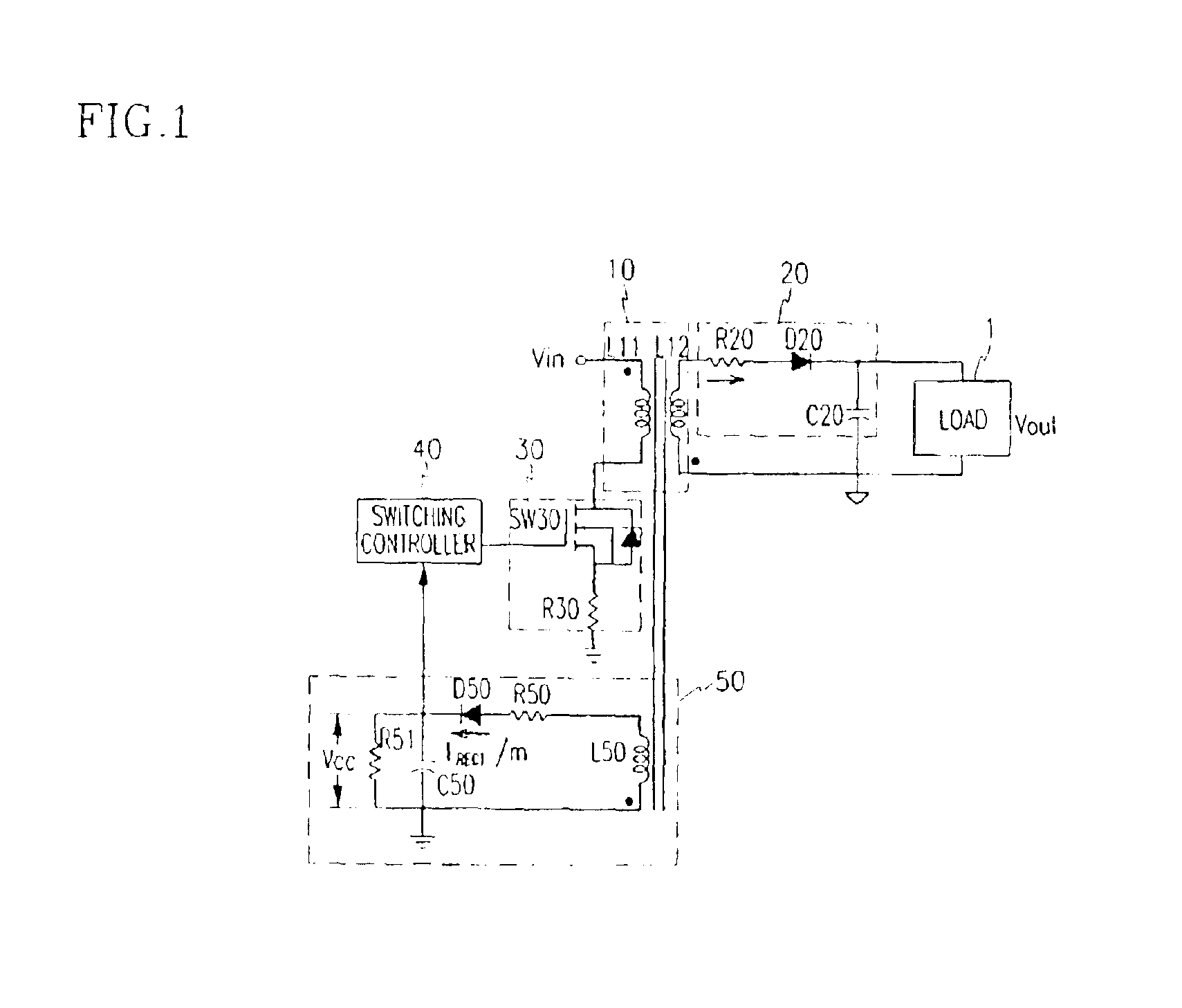
FIG. 1 illustrates an embodiment of a flyback converter, which detects an output voltage using a separate detecting coil at the primary winding to reduce power consumption.

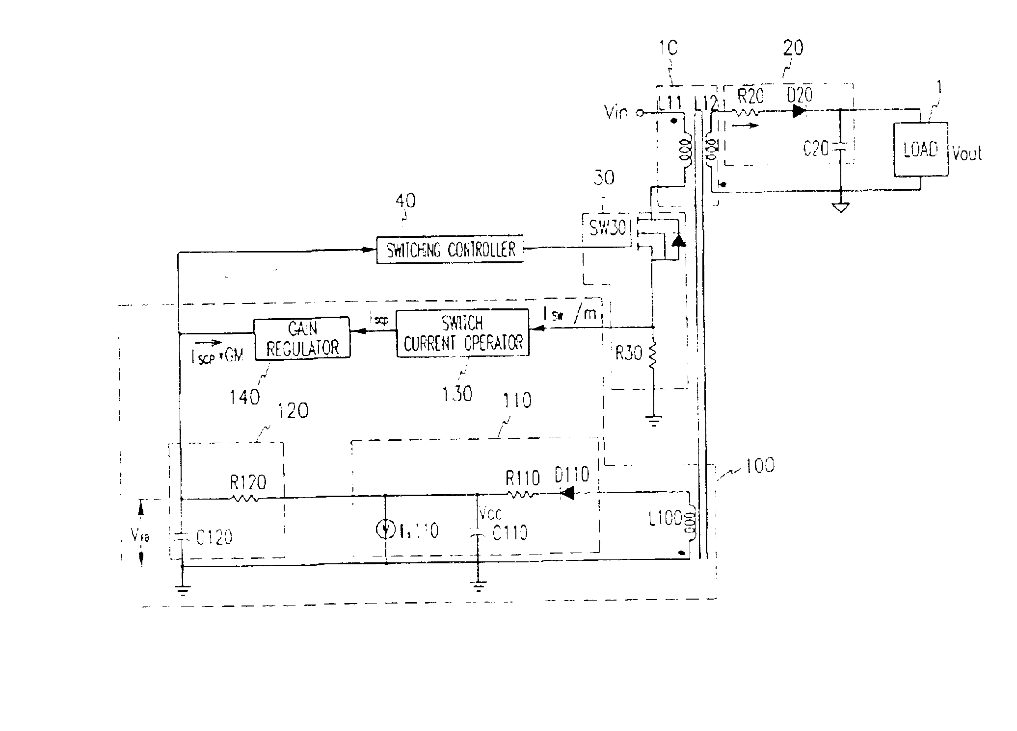
In some embodiments of the flyback converter, a transformer 10 changes an input voltage to a predetermined level according to a winding ratio of a primary coil to a secondary coil. An output unit 20 rectifies an output voltage signal of the transformer 10 into a DC voltage to drive a load 1. A switch 30, coupled to the primary coil of the transformer 10, controls the on / off state of the power at the primary coil according to an input switching control signal. A feedback unit 50 detects the voltage signal output from the transformer 10 to the output unit 20 and generates a corresponding signal. A switching controller ...


PUM

PropertyMeasurementUnit
power consumptionaaaaaaaaaa
sizeaaaaaaaaaa

Abstract

A flyback converter detects an output voltage at the primary coil without using a photo coupler and provides an essentially constant output voltage independent of the load size, thereby minimizing the number of additional coils used in the transformer circuit to realize simple construction and providing accurate power control. In one embodiment, the flyback converter includes: a transformer for changing an input voltage to a predetermined level according to a winding ratio; an output unit for rectifying the voltage signal output from the transformer into a DC signal to drive a load; a switch coupled to the primary coil of the transformer for controlling the on / off state of a power at the primary coil according to a switching control signal; a feedback unit generating a feedback signal and detecting a current of the switch to correct the feedback signal; and a switching controller operating according to the feedback signal.

Description

BACKGROUND OF THE INVENTION1. Field of the InventionThe present invention relates to power conversion. More specifically, the present invention relates to a flyback converter that detects an output voltage at the primary coil without using a photo coupler and provides an essentially constant output voltage independent of the size of a load, thereby minimizing the number of additional coils used in the transformer circuit.2. Description of the Related ArtA DC-to-DC converter is a device for transforming a DC voltage, which converts a DC input voltage to an AC voltage, and after boosting or reducing the voltage with a transformer, rectifies the AC voltage to produce a DC output voltage. DC-to-DC converters are classified as forward converters and flyback converters, depending on the construction of the transformer.A loss of power under a light load in a converter is controlled according to treaty provisions related to regulations for reducing energy consumption. Conventionally, power ...

Claims


Application Information

Patent Timeline
Patent Type & Authority Patents(United States)
IPC IPC(8): H02M3/335H02M3/24H01F38/42
CPCH02M3/33507H01F38/42
Inventor KIM, JUNG-WONHUH, DONG-YOUNG
Owner FAIRCHILD SEMICON CORP
Learn More