
Optical system for the rotation of images taken by a film camera about the optical axis

an optical system and film camera technology, applied in the field of optical systems, can solve problems such as reduction in optical performance, and achieve the effects of high optical system dynamics, fine adjustment, and no reduction of optical performance of picture systems

Inactive Publication Date: 2005-01-18
ARNOLD & RICHTER CINE TECHN & BETRIEBS
View PDF14 Cites 6 Cited by
  • Summary
  • Abstract
  • Description
  • Claims
  • Application Information

AI Technical Summary

Benefits of technology

The object of the invention is therefore to integrate an image-rotating optical system in the picture system of a film camera without reducing the optical performance of the picture system, which has an extremely fine adjustment and very high optical system dynamics, and which takes up less structural space and ensures minimal noise development.
The solution according to the invention makes it possible to integrate an image-rotating optical system into the picture system of a film camera without reducing the optical performance of the picture system and which has a highly accurate adjustment and very high optical system dynamics which takes up minimal structural space, ensures a high operating comfort and high adjusting speeds during image rotation with a minimal level of noise.
Through the direct rigid connection of a ring-shaped drive motor and a position sensor with the image-rotating optical system no mechanical play occurs and due to the absence of a mechanical gearing means the noise level is significantly reduced. Furthermore the structural space required is less than in an arrangement with drive motors arranged externally and eccentrically relative to the optical system. Through the direct installation of a ring-shaped drive motor about the image-rotating optical element no external and eccentric forces are introduced into the optical system which could lead to a reduction in the optical performance, for example preventing centering of the optical system.
By arranging the rear fastening flange of the optical system between the transmission lens and the fixed prism it is possible to arrange the fixed prism at least in part inside the camera housing so that a corresponding shortening and integration of the optical system in the film camera is possible.
Since in particular zoom lenses have the property that in most embodiments the exit pupil position changes severely when changing the focal width, it is advantageous to carry out an adaptation of the optical system to different focal widths. This can be undertaken during operation for example through a corresponding adaptation of a field lens system.
By using a motorised drive for rotating the image-rotating optical system it is possible not only to reach very high adjusting speeds but also adjusting movements synchronised with the film camera in the transport phase of the moving film. Therefore it is possible to undertake a change in the horizon line of the film camera between the exposure of successive individual images whereby the direct installation of the drive in coaxial form means that no external and eccentric forces are introduced into the system which could lead to a reduction in the optical performance.

Problems solved by technology

Through the direct installation of a ring-shaped drive motor about the image-rotating optical element no external and eccentric forces are introduced into the optical system which could lead to a reduction in the optical performance, for example preventing centering of the optical system.

Method used


Image

  • Optical system for the rotation of images taken by a film camera about the optical axis
  • Optical system for the rotation of images taken by a film camera about the optical axis
  • Optical system for the rotation of images taken by a film camera about the optical axis

Examples


Embodiment Construction

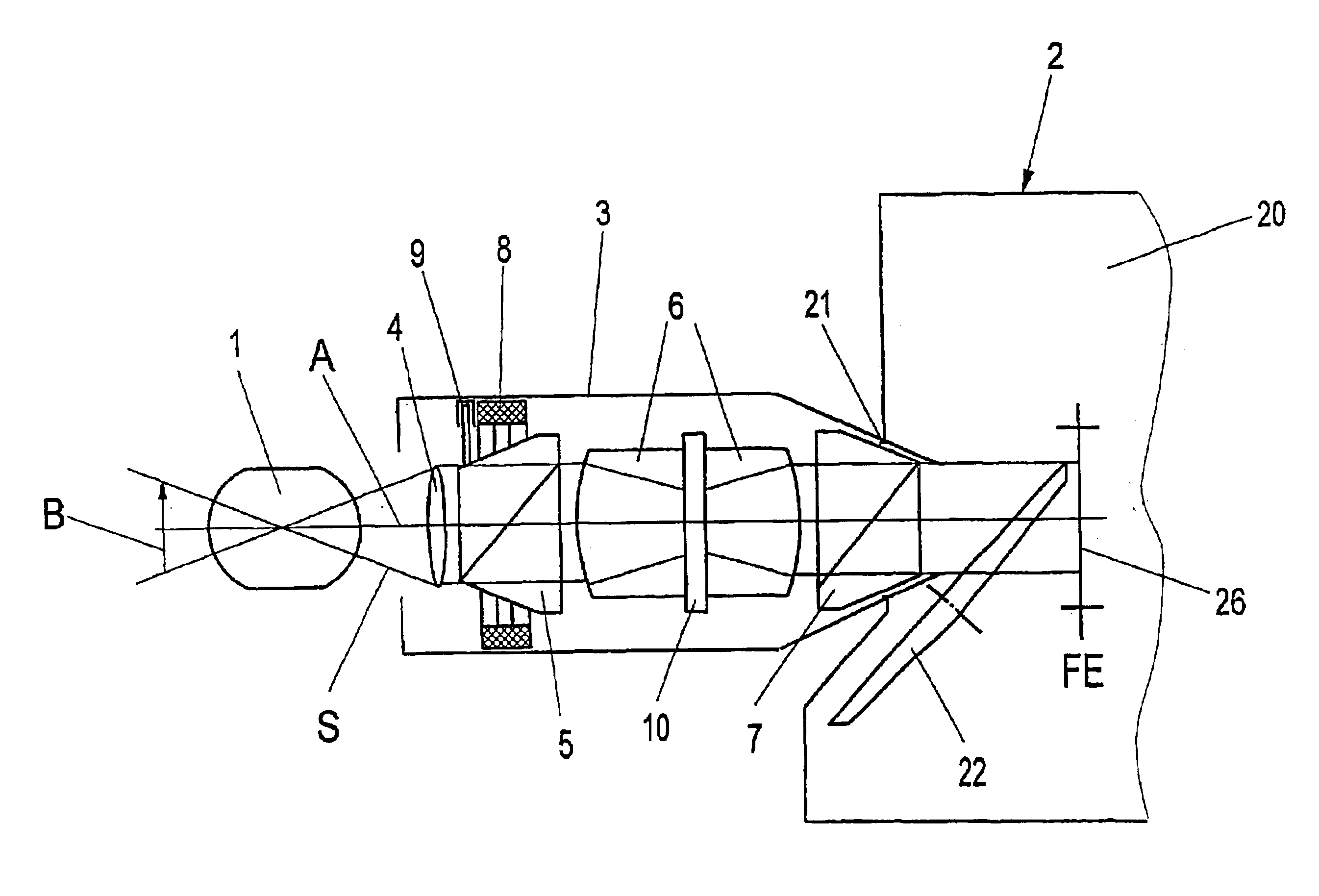
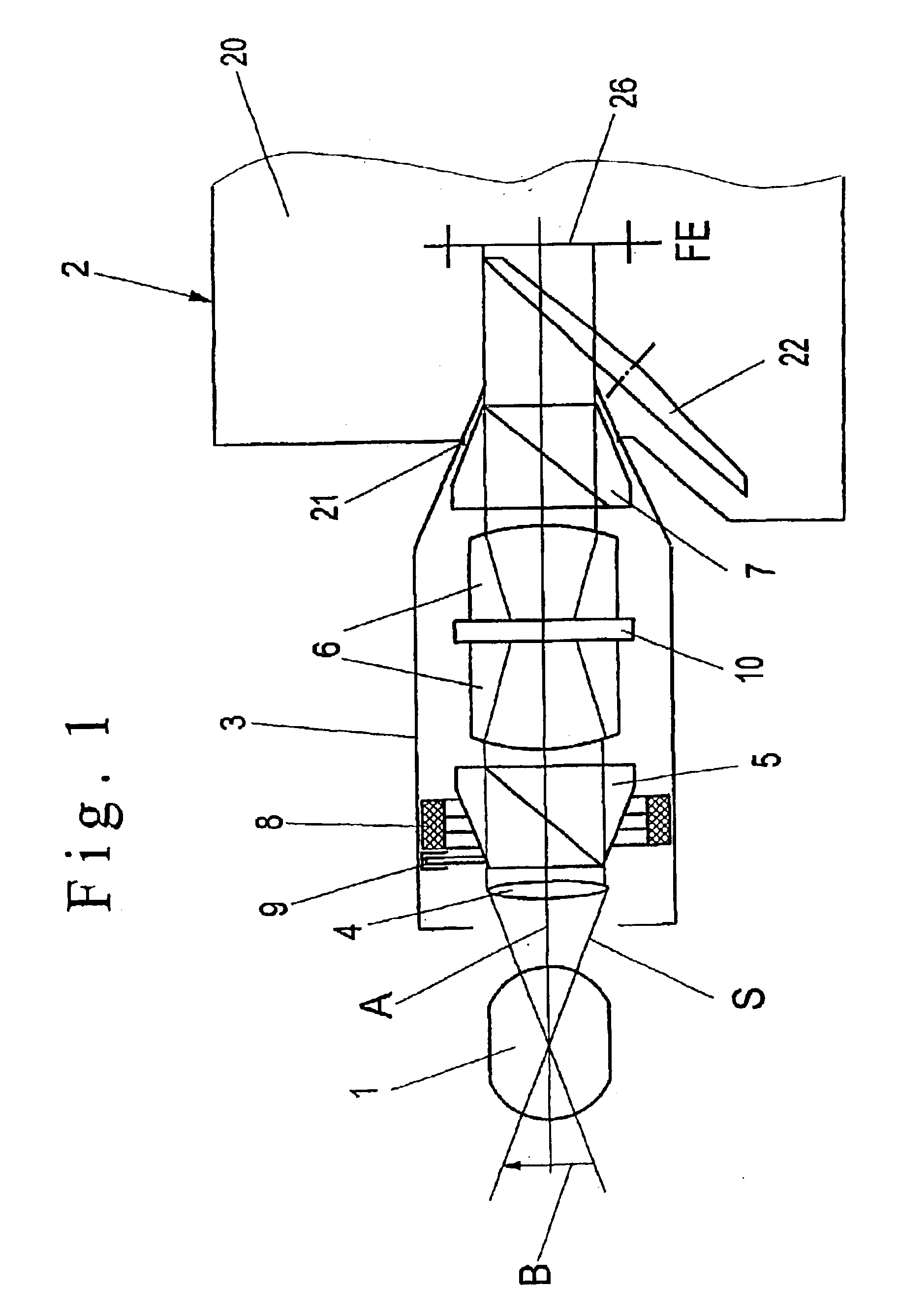
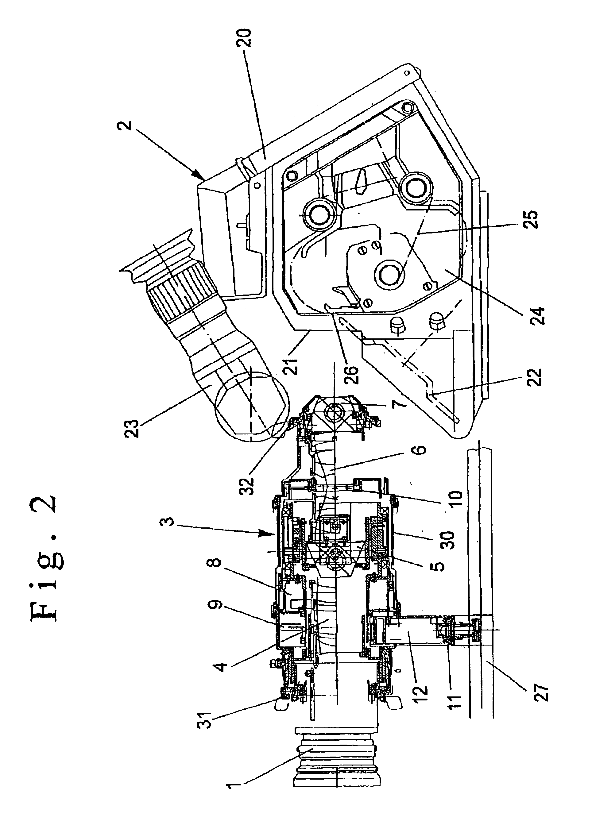
The basic construction of an image-rotating optical system 3 mounted between a recording lens 1 and a film camera 2 and shown diagrammatically in FIG. 1 has in the direction of the recording beam path behind the recording lens 1 a field lens which in a preferred embodiment according to FIGS. 2 and 3 is designed as a field lens parcel.

In the recording beam direction behind the field lens there is a rotatable prism 5 which can consist for example of a Schmidt-Pechan prism. The rotatable prism 5 is connected to an adjusting motor 8 which consists of a ring-shaped drive motor for the rotation of the rotatable prism 5 about the optical axis A. In order to detect the relevant rotational angle of the rotatable prism 5 relative to a reference position there is a position sensor 9 which consists for example of an optoelectronic position sensor with a high resolution of the angle degrees to be detected.

As an alternative to the rotatable prism or in combination with a rotatable prism it is pos...


PUM


Abstract

The invention relates to an optical system for the rotation of images taken by a film camera about an optical axis, having a controller device for the rotation of images with an adjusting motor and a position sensor for recording the rotation angle of the image-rotating optical system. In addition, the possibility of displacing the optical system in at least one axial direction is provided.

Description

FIELD OF THE INVENTIONThe invention relates to an optical system and more specifically to an optical system for the rotation of images taken by a film camera about an optical axis.BACKGROUND OF THE INVENTIONFrom DE 24 36 230 A1 an optical system is known for the rotation of images in a recording lens system for television cameras, movie film cameras and photographic cameras. The optical system contains a prism which serves for the rotation of the image and which is mounted between a forward lens and a rear lens of a relay-lens system, as well as a field lens which is mounted on a first focusing plane on which an image is created through an objective lens. The field lens has a focal distance such that the pupil of the relay-lens system conjugated to the opening of the objective lens can be arranged in the centre point of the beam path of the prism which is serving for the rotation of the image.From DE 3245 477 A1 an optical system is known for image rotation which has a projection le...

Claims


Application Information

Patent Timeline
IPC IPC(8): G02B27/64G03B19/20G03B19/00G02B17/02G03B19/18
CPCG03B19/20G02B27/642
Inventor FILOUS, PAVELTRAUNINGER, WALTERHAUBMANN, MICHAEL
Owner ARNOLD & RICHTER CINE TECHN & BETRIEBS
Learn More