Eureka AIR delivers breakthrough ideas for toughest innovation challenges, trusted by R&D personnel around the world.

Reinforced composite vehicle load floor of the cellular core sandwich-type

a composite structure and load floor technology, applied in vehicle arrangements, roofs, transportation and packaging, etc., can solve the problems of high manufacturing cost and complexity, low level of automation, and typical heavy structure, and achieve simple and cheap manufacturing and high throughput

Inactive Publication Date: 2005-01-18
GLOBAL IP HLDG
View PDF17 Cites 125 Cited by
  • Summary
  • Abstract
  • Description
  • Claims
  • Application Information

AI Technical Summary

Benefits of technology

An object of the present invention is to provide a reinforced composite vehicle load floor of the cellular core sandwich-type which can be made simply and cheaply, and can be implemented at high throughputs.

Problems solved by technology

Such structure is typically very heavy and manufacturing costs and complexity are high, therefore improvements are desirable.
However, the non-uniformness of the mechanical stresses to which they are subjected sometimes makes it necessary to form local reinforcing plies at those places in said panels where the mechanical stresses are greatest.
That “lamination” technique, and in particular the “laying up” operation, is characterized by a very low level of automation, and a large labor input.
As a result, that technique is very costly and cannot be used at the high production throughputs implemented in many fields such as the automobile industry.
As noted in the above-mentioned '560 and '604 patents, although thermoset composites have excellent mechanical properties, they suffer from several disadvantages: thermoset matrices have relatively limited elongation, the thermoset precursors are a source of undesirable volatile organic compounds (VOCs), the composites cannot be reshaped or recycled, and their production rates are limited.

Method used


Image

  • Reinforced composite vehicle load floor of the cellular core sandwich-type
  • Reinforced composite vehicle load floor of the cellular core sandwich-type
  • Reinforced composite vehicle load floor of the cellular core sandwich-type

Examples


Embodiment Construction

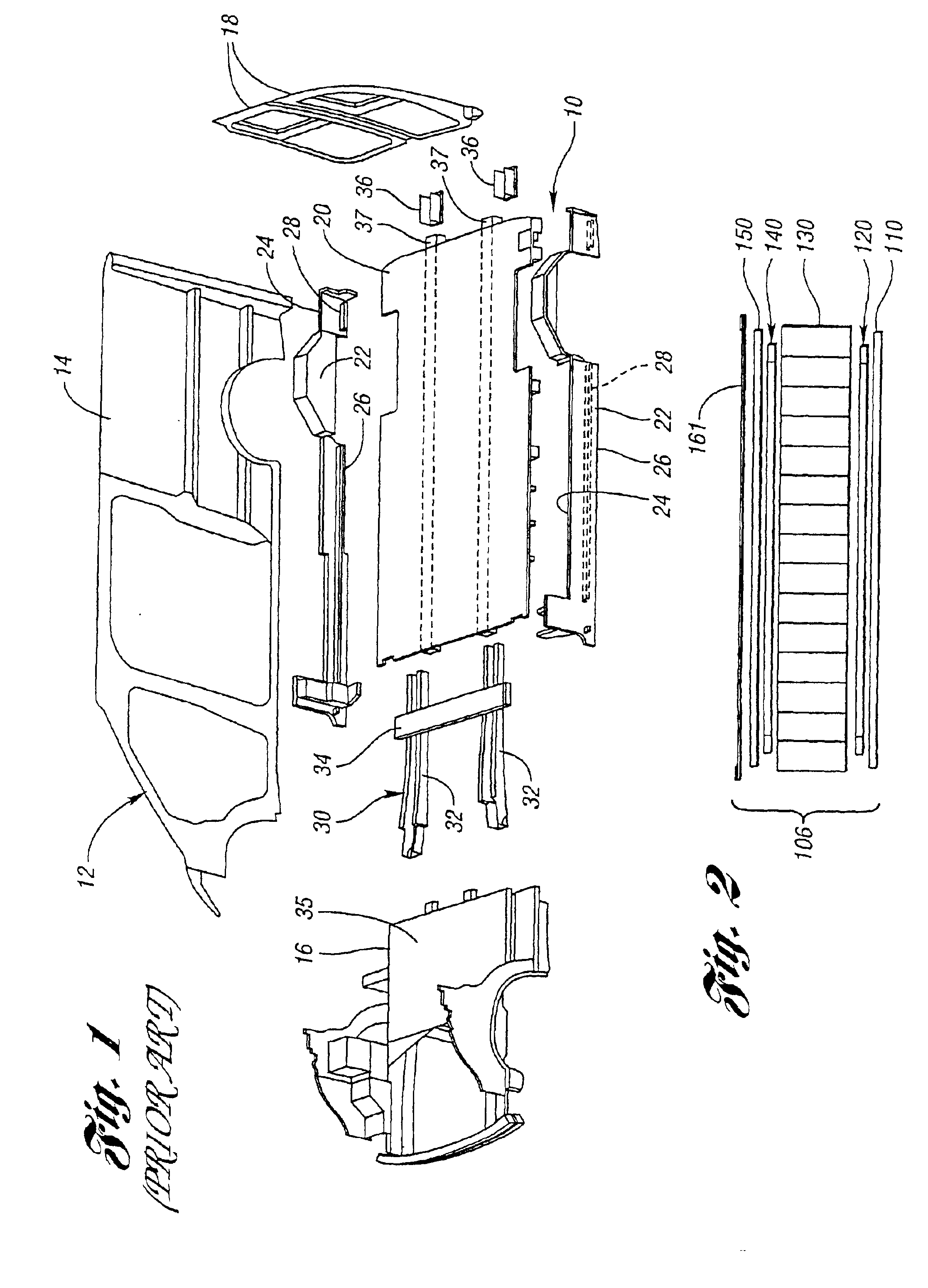
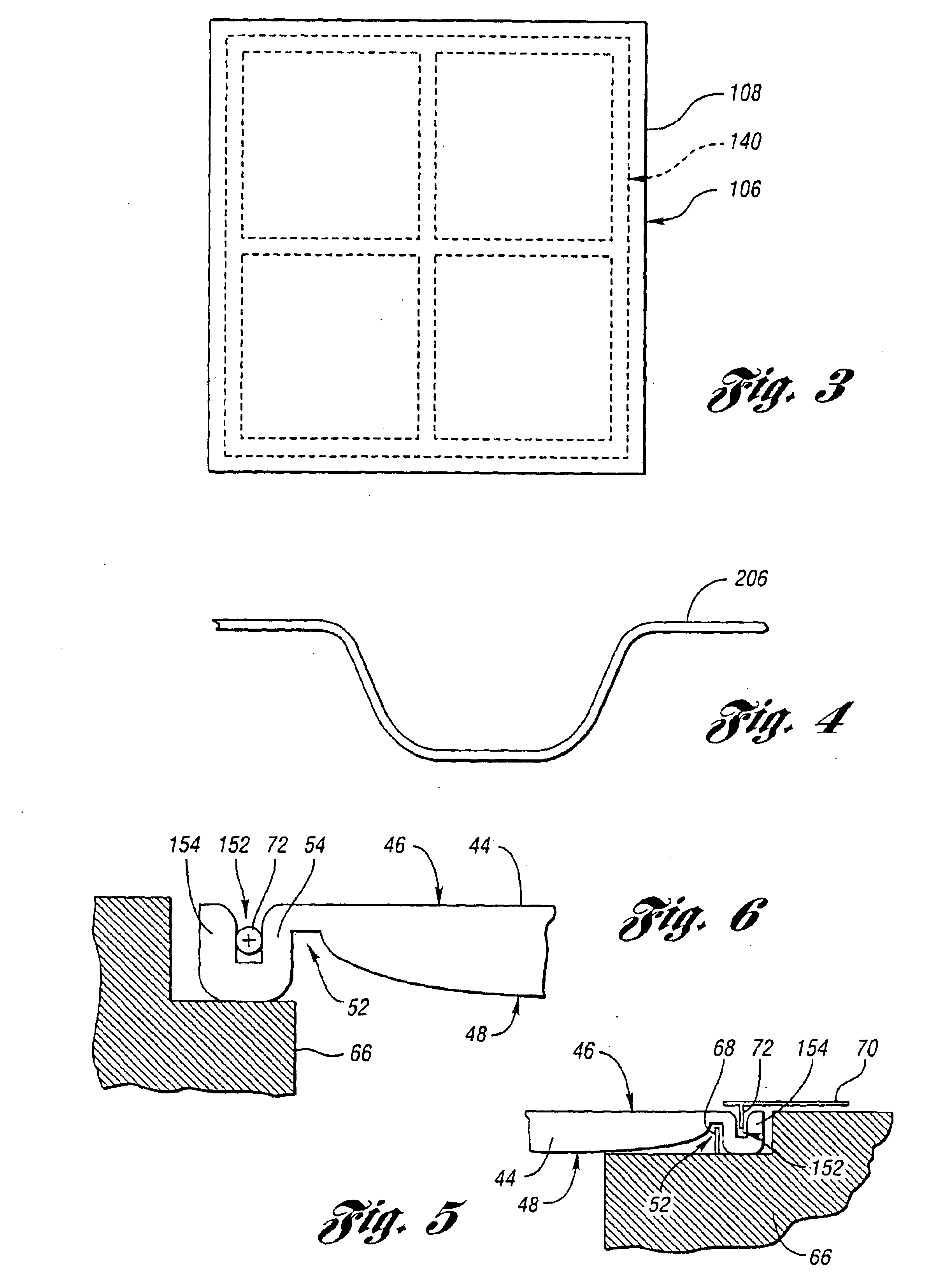
FIG. 2 shows a stack formed during a first step of a method of making a reinforced composite vehicle load floor of the cellular core sandwich-type of the present invention. The first step is used to make the load floor, generally indicated at 106 in FIG. 2.

In this example, the stack is made up successively of: a bottom skin 110 made of a reinforced thermoplastics material; a lower skeletal frame structure of reinforcing slats 120 each of which may be made of a reinforced thermoplastic composite or pultrusion; a cellular core 130 made of thermoplastics material; an upper skeletal frame structure of reinforcing slats, generally indicated at 140, each of which may be made of a reinforced thermoplastic composite or pultrusion; and a load-bearing upper skin 150 made of a reinforced thermoplastic material. Alternatively, the slats may be made of other types of pultrusions or other materials such as metal.

In addition, the stack includes an outer covering layer 161 made of a woven or non-wo...


PUM


Abstract

The invention relates to reinforced composite vehicle load floors of the sandwich-type having a cellular core. In a method for making a load floor of the invention, a stack is formed that is made up of: a load-bearing upper skin made of a reinforced thermoplastics material; an upper skeletal frame structure of reinforcing slats each of which is made of a reinforced thermoplastic composite or pultrusion; a cellular core made of a thermoplastic material; a lower skeletal frame structure of reinforcing slats each of which is also made of a reinforced thermoplastic composite or pultrusion; and a bottom skin made of a reinforced thermoplastic material. Each of the frame structures of reinforcing slats has a surface area that is smaller than the surface area of each of the skins. The frame structures of reinforcing slats are positioned symmetrically about a plane formed by the cellular core against the skins.

Description

BACKGROUND OF THE INVENTION1. Field of the InventionThe present invention relates generally to vehicle load floors of sandwich-type composite structure having a cellular core and, in particular, to such load floors whose structure is reinforced locally.2. Background ArtReferring to the drawings and, in particular, to FIG. 1, a prior art underbody assembly 10 is shown for a motor vehicle, generally indicated at 12, in accordance with U.S. Pat. No. 6,126,219. The motor vehicle 12 includes a pair of body side assemblies 14 operatively connected to sides of the underbody assembly 10. It should be appreciated that only one body side assembly 14 is illustrated.The motor vehicle 12 includes a front end assembly 16 operatively connected to a forward or front end of the underbody assembly 10. The motor vehicle 12 also includes a pair of rear cargo doors 18 operatively adjoined to a rear or back end of the underbody assembly 10. It should be appreciated that the motor vehicle 12 includes a ro...

Claims


Application Information

Patent Timeline
IPC IPC(8): B62D29/00B62D29/04B62D25/20
CPCB62D25/2054B62D29/041Y10T428/24165
Inventor PREISLER, DARIUS J.
Owner GLOBAL IP HLDG
Why Eureka
Eureka Blog
Learn More