
System and method of water treatment

a water treatment system and water treatment technology, applied in the field of water systems and methods, can solve the problems of limited environmental hazards, failure to disclose, and less efficient vacuum mechanism for removing dissolved oxygen from ballast water, and achieves low manufacturing cost and low price of sale. , the effect of easy and efficient manufacturing and marketing

Inactive Publication Date: 2005-01-11
HRL LAB +1
View PDF24 Cites 46 Cited by
  • Summary
  • Abstract
  • Description
  • Claims
  • Application Information

AI Technical Summary

Benefits of technology

The present invention provides an improved system and method for water treatment using oxygen stripping gas. The system includes an injector means and a transfer piping means to deliver the gas to the water. A re-circulation means is optionally included to monitor the level of oxygen in the treated water. The invention also allows for the efficient treatment of water with oxygen stripping gas, reducing the negative environmental effects that may occur when releasing large amounts of deoxygenated water into surrounding waterways. The invention provides a new and improved system and method for water treatment that offers more advantages and benefits than previous methods.

Problems solved by technology

Such treatment limits the environmentally hazardous effects that may result when the water is later released into an environment that is ecologically different from that in which the water was originally obtained.
However, the Browning '508 patent does not use stripping gas to deoxygenate the ballast water and consequently fails to disclose any corrosion inhibition properties, and has further drawbacks of using a less efficient vacuum mechanism to remove the dissolved oxygen from the ballast water.
However, the Rodden '778 patent does not provide for corrosion, and fails to use the more efficient venturi-injector facilitated means of to treat the ballast water.
However, the Gill '451 patent does not allow for water treatment without the occurrence of a chemical reaction, and does not provide for any corrosion inhibition properties.
However, neither the '282 nor the '116 patent provides for a more efficient venturi injector-facilitated delivery of stripping gas to deoxygenate the ballast water and have the further disadvantages of failing to provide for corrosion inhibition effects during the removal of dissolved oxygen from the water.
However, the Decker '842 patent, although providing an efficient ozone-based treatment system using a venturi injector, does not disclose the treatment of ballast water on a vessel nor does the '842 patent offer the even greater advantages obtained using an oxygen stripping gas such as increased efficiency and corrosion inhibition.
However, the Hartwig '052 patent does not disclose the injection of an oxygen stripping gas into the water through venturi injectors in order to deoxygenate the water, and has the additional deficiency of failing to provide for any corrosion inhibition effects during the process described.
However, the Savard '111 patent does not use an oxygen stripping gas for the deoxygenation of water, preferably but optionally ballast water, further fails to provide for corrosion inhibition.
However, the Nold '983 patent requires cavitation of the liquid and does not use a venturi injector to more efficiently enhance the degassing of the liquid,
While the above-described inventions fulfill their particular objectives and requirements, the aforementioned patents do not describe a system and method for water treatment which allows a vessel to treat ballast water that is being transported from one port area to another while providing corrosion inhibition.
The aforementioned patents and other water treatment systems and methods currently known in the art make no provisions for the treatment of water using an injector means to facilitate stripping gas deoygenation while also providing corrosion inhibition.

Method used


Image

  • System and method of water treatment
  • System and method of water treatment
  • System and method of water treatment

Examples


Embodiment Construction

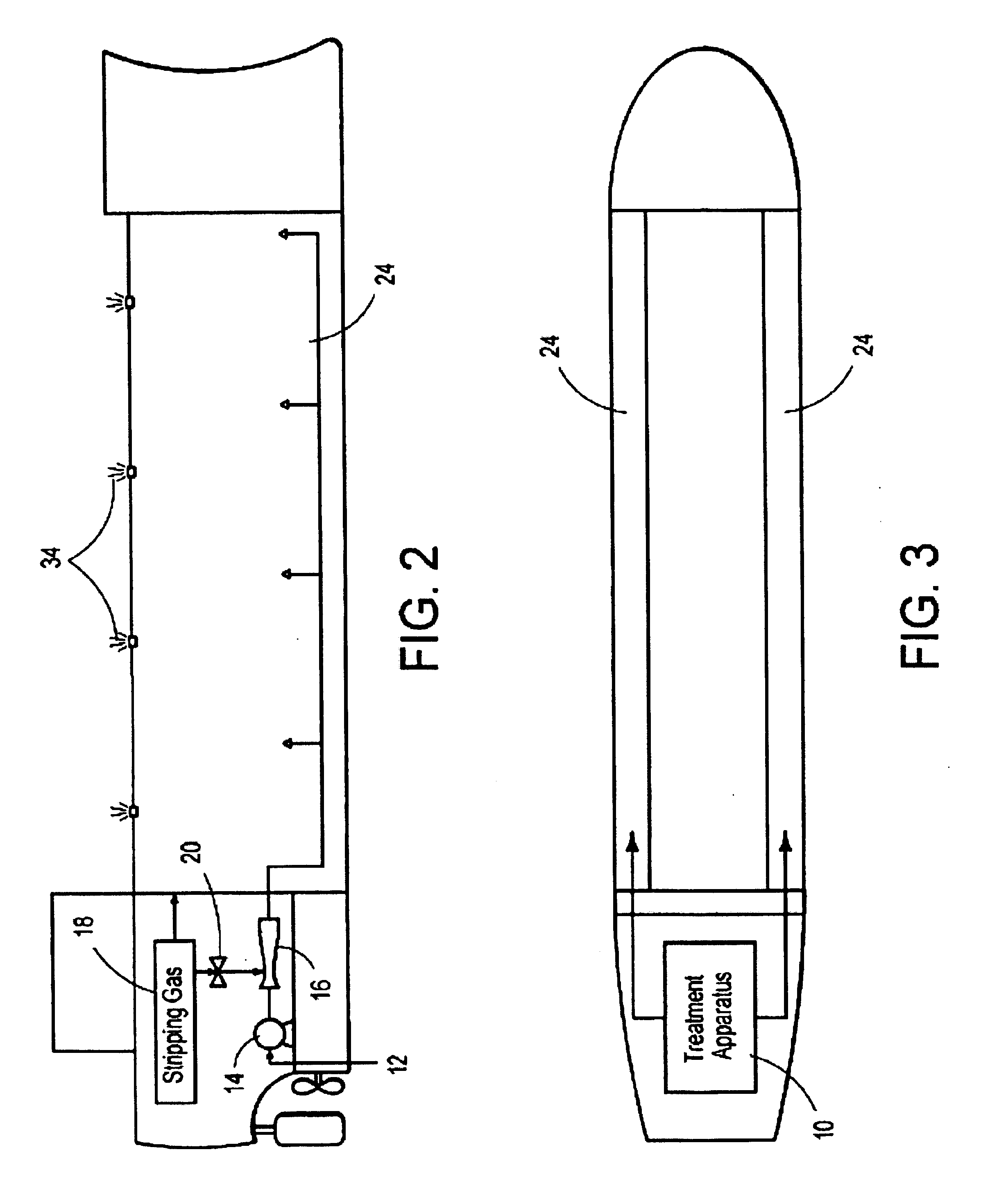
Referring now to the drawings, and particularly to FIGS. 1-5, a current embodiment of the system and method of water treatment of the present invention is shown and generally designated by the reference numeral 10.

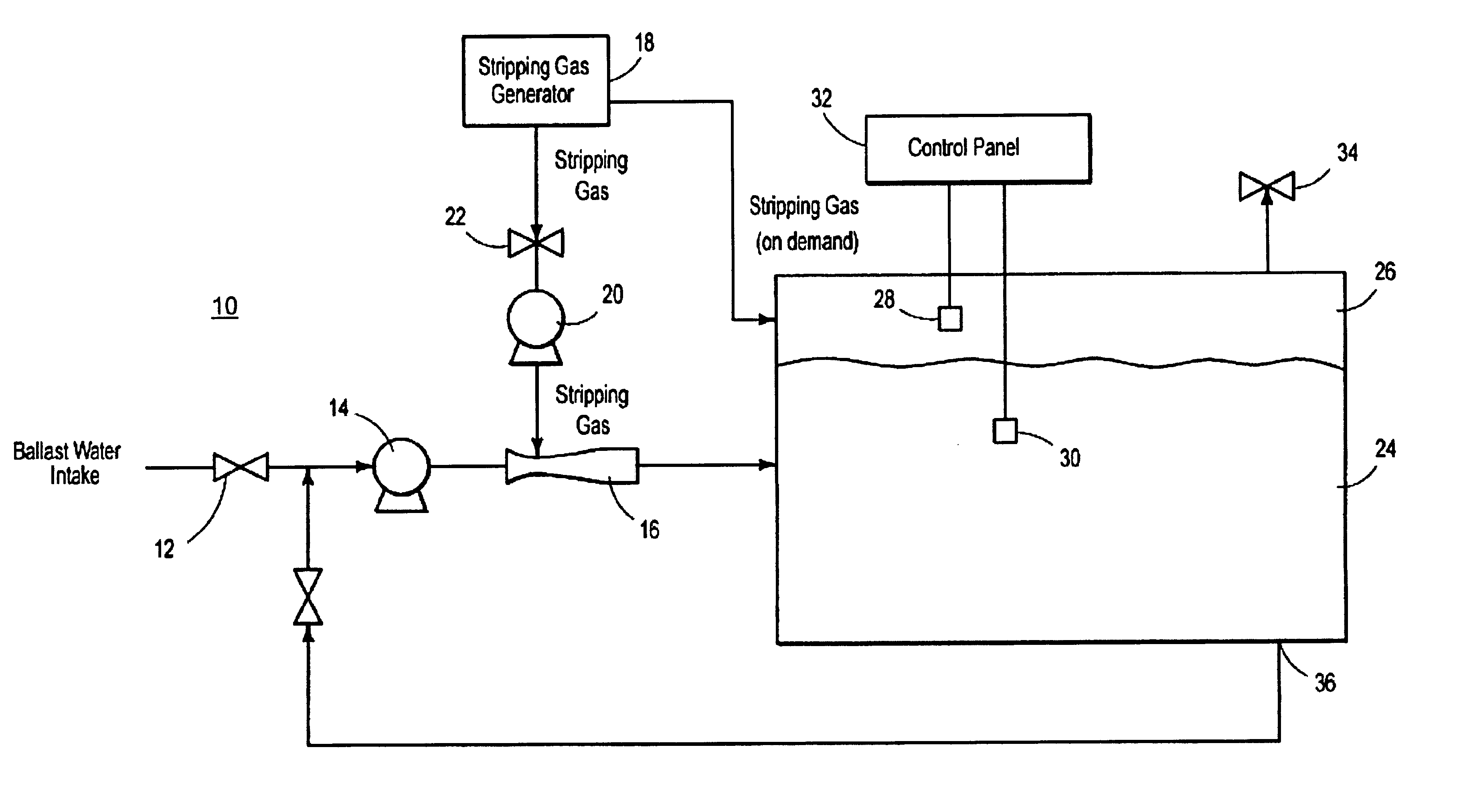
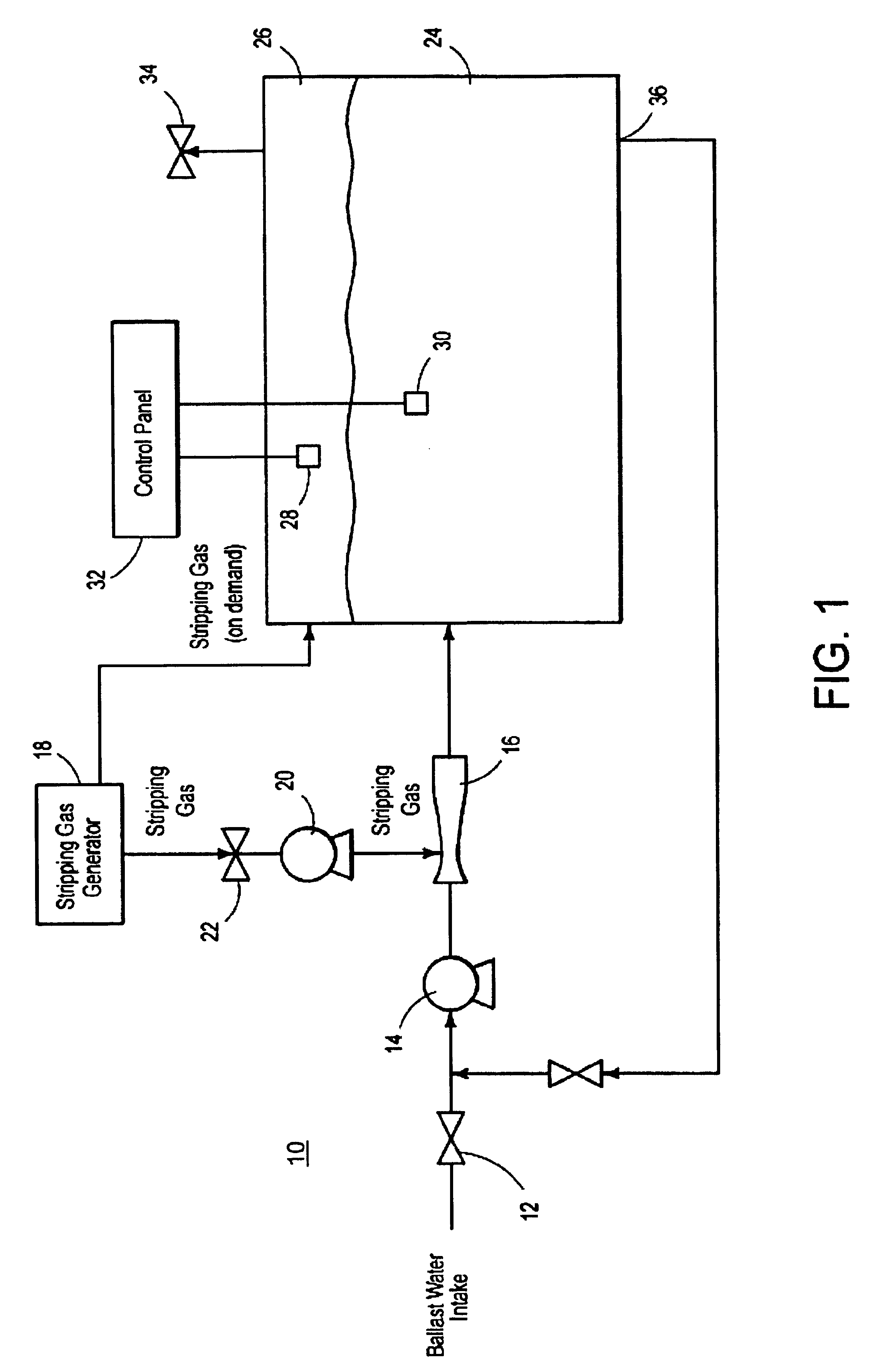
In FIG. 1, basic flow diagram of a new and improved system for water treatment using stripping gas deoxygenation 10, which allows a vessel to treat water that is being transported from one port area to another while providing for corrosion inhibition is illustrated and will be described. More particularly, the system for water treatment using stripping gas deoxygenation 10 has a water intake means 12 though which water enters from outside a vessel. The water is then pumped through a pump means, such as, but not limited to, a ballast pump 14, into an inlet port on an injector means 16, such as a venturi injector. Oxygen stripping gas that is obtained from a stripping gas source 18 is delivered to the inlet port of the injector means 16 which is facilitated by a booster blow...


PUM

PropertyMeasurementUnit
corrosionaaaaaaaaaa
stabilityaaaaaaaaaa
areaaaaaaaaaaa

Abstract

The present invention generally offers a system and a method that allows a vessel to treat water while providing corrosion inhibition. An oxygen stripping gas source produces oxygen stripping gas that may be pumped directly to, preferably but optionally, a venturi injector, or may first be pumped into an empty tank and then delivered to the injector means. Water being pumped through the injector via a transfer piping means comes into contact with the oxygen stripping gas, and dissolved oxygen in the water transfers to micro-fine stripping gas bubbles generated by the injector. The water and the micro-fine bubbles are pumped from the injector and into the tank, where the micro-fine bubbles float to the surface, and the oxygen is released into the tank's headspace. The deoxygenated water may be re-circulated through the system for additional deoxygenation or released from the tank into the surrounding waterways.

Description

BACKGROUND OF THE INVENTION1. Field of the InventionA system and method of water treatment using a venturi injector facilitates the removal of dissolved oxygen from water thereby reducing the population of undesirable aquatic organism present in the water while inhibiting corrosion. The system and method of water treatment has particular utility for use in connection with a vessel by allowing the vessel to treat ballast water that is being transported from one port area to another, thereby limiting environmentally adverse effects, while inhibiting corrosion. The system and method of water treatment may have other uses, such as in oil production.For instance, before a ship leaves a port empty, or partially loaded, it takes on water into ballast tanks to maintain stability and adjust buoyancy. In virtually every case, this ballast water will contain living organisms which are affected by levels of dissolved oxygen in the water. When the ship reaches its destination and prepares to loa...

Claims


Application Information

Patent Timeline
Patent Type & Authority Patents(United States)
IPC IPC(8): B01D19/00C02F1/20
CPCB01D19/0005C02F1/20C02F2303/08C02F2303/04C02F2103/008
Inventor MCNULTY, PETER DRUMMOND
Owner HRL LAB
Learn More