
Apparatus and method for testing rotational balance of crankshaft

a technology of rotating balance and crankshaft, which is applied in the direction of liquid/fluent solid measurement, machines/engines, instruments, etc., can solve the problems of predetermined rotational unbalance being intentionally left unremoved, inability to accurately balance the crankshaft as a whole, and great oscillation of the crankshaft, etc., to achieve accurate measurement of the rotational balance condition of each crankshaft, facilitate automatic measurement of rotational balance condition, and accurately measure the rotational balance condition of each crank

Inactive Publication Date: 2005-01-11
HONDA MOTOR CO LTD +1
View PDF4 Cites 10 Cited by
  • Summary
  • Abstract
  • Description
  • Claims
  • Application Information

AI Technical Summary

Benefits of technology

The present invention provides a crankshaft rotational balance testing apparatus and method that can accurately measure the rotational balance condition of crankshafts even where there are errors in the phases of crankpins. The apparatus and method involve measuring centrifugal force variation information of the crankshaft, measuring errors in the rotational phases of crankpins, creating dummy information that represents rotational unbalance components, and determining the initial rotational unbalance value of the crankshaft. This invention can automate the measurement of rotational balance and accurately measure the rotational balance condition of each crankshaft.

Problems solved by technology

In some cases, predetermined rotational unbalance is intentionally left unremoved, i.e. preset, on rotating members, such as crankshafts, when adjusting dynamic rotational balance conditions of the rotating members, for the following reasons.
In the case of a crankshaft of an engine, for example, inertial force of the crankshaft would not appropriately balance as a whole even if the crankshaft itself has been adjusted independently into perfect rotational balance, due to the fact that pistons, connecting rods, etc. are connected with the crankshaft.
Such unbalanced inertial force would cause great oscillation of the crankshaft during rotation about the crankshaft's rotation axis.
For these reasons, the first adjustment scheme necessitates preparation of various types of dummy rings and encounters considerable difficulties in automatizing the rotational balance condition measurement.
However, if a crankpin to be tested has rotational phase errors beyond an allowable range, the measured results would undesirably contain great errors so that unsatisfactory balance adjustment, incapable of appropriately removing undesired rotational unbalance, tends to be performed on the crankshaft.

Method used


Image

  • Apparatus and method for testing rotational balance of crankshaft
  • Apparatus and method for testing rotational balance of crankshaft
  • Apparatus and method for testing rotational balance of crankshaft

Examples


Embodiment Construction

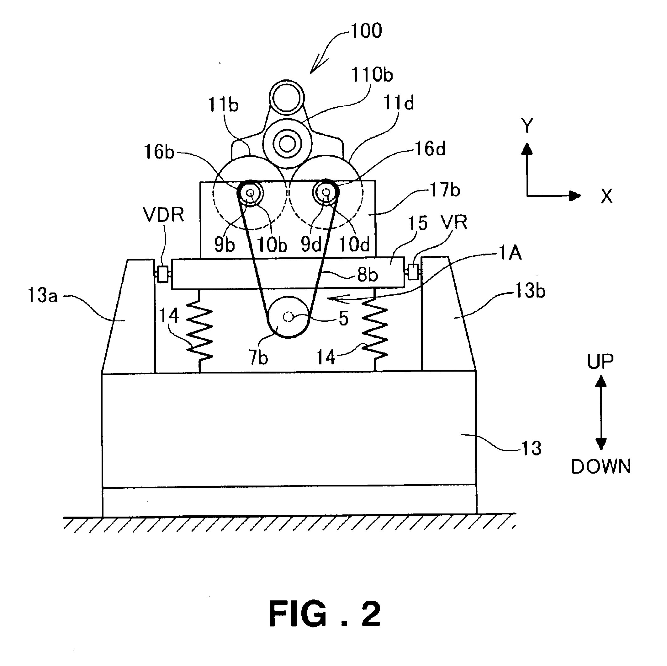
Initial reference is made to FIG. 1 showing in front elevation a measurement section of a crankshaft rotational balance testing apparatus in accordance with an embodiment of the present invention, and to FIG. 2 showing in side elevation the crankshaft rotational balance testing apparatus of FIG. 1.

In the crankshaft rotational balance testing apparatus shown in FIGS. 1 and 2, the measurement section 1 includes a framework that includes a base 13, damper springs 14 extending vertically upward from the upper surface of the base 13 and an oscillatable measuring table 15 supported by the springs 14 above the base 13. The measurement section 1 also includes a crankshaft rotation mechanism 1A, a centrifugal force measuring unit 1B, and a rotational phase error measuring unit 1C.

The crankshaft rotation mechanism 1A rotates a to-be-tested crankshaft about the rotation axis of the crankshaft. The rotation mechanism 1A includes drive shaft bearings 12a and 12b secured to the underside of the m...


PUM


Abstract

Measurement is made of centrifugal force produced on a crankshaft to be tested that is being rotated about its rotation axis, to provide centrifugal force variation information of the crankshaft. Also, measurement is made of errors in respective rotational phases of crankpins of the crankshaft about rotation axes of the crankpins. Dummy information, comprising rotational unbalance data representative of rotational unbalance components to be removed from the centrifugal force variation information of the crankshaft, is created using the measured errors in the respective rotational phases. Then, an initial rotational unbalance value of the crankshaft is determined, using the dummy information and the centrifugal force variation information of the crankshaft.

Description

FIELD OF THE INVENTIONThe present invention relates to an improved crankshaft rotational balance testing apparatus and method for measuring rotational balance conditions of crankshafts.BACKGROUND OF THE INVENTIONIn some cases, predetermined rotational unbalance is intentionally left unremoved, i.e. preset, on rotating members, such as crankshafts, when adjusting dynamic rotational balance conditions of the rotating members, for the following reasons. In the case of a crankshaft of an engine, for example, inertial force of the crankshaft would not appropriately balance as a whole even if the crankshaft itself has been adjusted independently into perfect rotational balance, due to the fact that pistons, connecting rods, etc. are connected with the crankshaft. Such unbalanced inertial force would cause great oscillation of the crankshaft during rotation about the crankshaft's rotation axis. To address the inconvenience, it has been known to make balance adjustment of a crankshaft such ...

Claims


Application Information

Patent Timeline
Patent Type & Authority Patents(United States)
IPC IPC(8): G01M1/24G01M1/00G01M1/16
CPCG01M1/24
Inventor TAMURA, EIJIYAMAZAKI, YASUNORIMAKIN, JOSEPHMIURA, HIROKI
Owner HONDA MOTOR CO LTD
Learn More