
Liquid crystal display panel

a liquid crystal display and panel technology, applied in static indicating devices, instruments, non-linear optics, etc., can solve problems such as corner blurs, and achieve the effect of preventing the generation of corner blurs in the corner portions of the lcd panel

Inactive Publication Date: 2005-01-04
LG DISPLAY CO LTD
View PDF9 Cites 37 Cited by
  • Summary
  • Abstract
  • Description
  • Claims
  • Application Information

AI Technical Summary

Benefits of technology

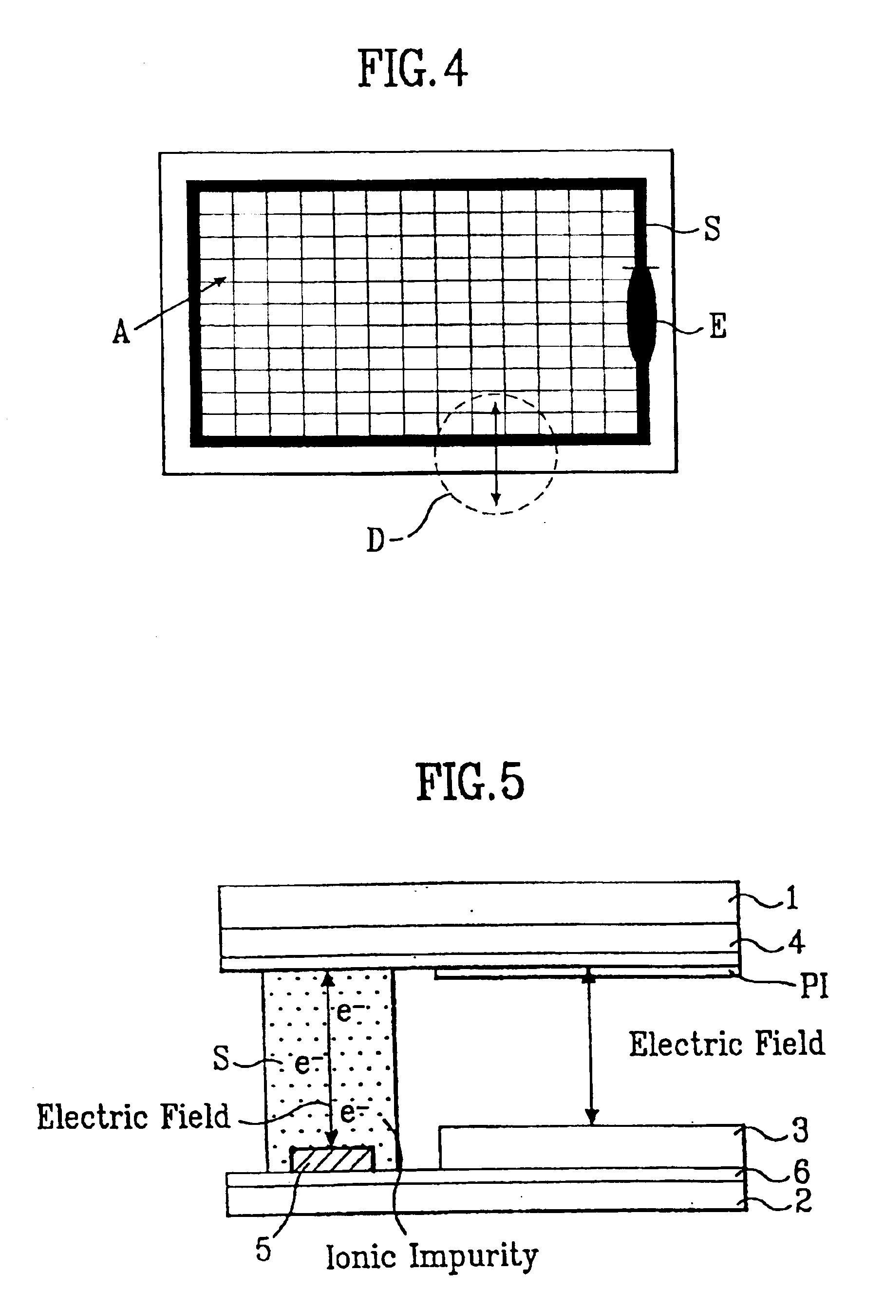
An object of the invention is to provide an LCD panel in which electrodes are arranged so that the electrodes can apply voltage to the lower part of a seal pattern to prevent ionic impurities from penetrating into an active area and to capture ionic impurities from the active areas.
Also, it is another object of the invention to provide an LCD panel that provides spaces or projections in corner portions of a seal pattern to collect impurities within the panel so that the generation of blur in the corner portions of an LCD panel can be prevented.

Problems solved by technology

First, impurity ions existing on the surfaces of the substrates are carried by the surface of the liquid crystal in a capillary phenomenon when the liquid crystal is injected in between the substrates. Accordingly, the impurity ions (e−) are deposited at the corner portions of the display panel in relatively larger amounts. Such impurity ions (e−) are activated at a high temperature of about 50 degrees and generate blurs at the corner portions of an operating LCD.
Second, ionic impurities existing within the seal pattern can migrate into the liquid crystal causing electric field distortion and thus generating blur in the active area A of a LCD. In other words, when the electric field is applied between the common electrode 4 and the pixel electrode 3 to induce the liquid crystal to have a different alignment, the preexisting ionic impurities (e−) in the seal pattern can penetrate into the liquid crystal in the active area A. The ionic impurities (e−) can then be adsorbed into the surface of the common electrode 4 and function as resistance components, so that electric field distortion will take place and result in blur in the active area A.

Method used


Image

  • Liquid crystal display panel
  • Liquid crystal display panel
  • Liquid crystal display panel

Examples


second embodiment

The LCD panel according to the invention includes an upper substrate and a lower substrate put together with a seal pattern S having a structure with projected corner portions in the seal area between the substrates, as shown in FIG. 6.

As described in the related art, the corner portions are areas with a high density of ionic impurities since preexisting ionic impurities within the panel are carried to the corner portions of the seal pattern by the injected liquid crystal. Therefore, the corner portions of the seal pattern S according to the second embodiment of the present invention are outwardly projected so that the ionic impurities can be collected within the projected portions at the corners of the seal pattern.

first embodiment

Of course, as in the invention, it is also effective to form the electrode pattern 5 between the seal pattern S and the lower substrate or on portions of the lower substrate adjacent to the seal pattern S. Also, the electrode pattern 5 can be formed on the lower substrate where an injection hole sealant is positioned.


PUM

PropertyMeasurementUnit
areaaaaaaaaaaa
areasaaaaaaaaaa
timeaaaaaaaaaa

Abstract

The invention relates to an LCD panel for preventing the generation of blur due to ionic impurities. The LCD panel comprises a first substrate having a common electrode; a second substrate having an active area; a seal pattern along the periphery of said active area between said first substrate and said second substrate; a liquid crystal layer between said first substrate and said second substrate in said active area; and an electrode pattern between said seal pattern and said second substrate. Alternatively, the seal pattern has outwardly projecting corner portions. An electric field is generated between the electrode pattern and the common electrode so that the ionic impurities are prevented from penetrating into the active area, and the ionic impurities in liquid crystal are captured in the seal pattern portion to prevent the generation of blur due to ionic impurities.

Description

The present invention claims the benefit of Korean Patent Application No. P2000-69455 filed in Korea on Nov. 22, 2000, which is hereby incorporated by reference.BACKGROUND OF THE INVENTION1. Field of the InventionThe present invention relates to a liquid crystal display device, more particularly, to a liquid crystal display panel in which blur due to ionic impurities generated during the sealing process is avoided.2. Background of the Related ArtIn general, the liquid crystal display (LCD) panel comprises upper and lower glass substrates with liquid crystal sealed in between the upper and lower glass substrates.The lower glass substrate has a plurality of gate lines arranged in one direction with a certain distance between them and data lines arranged along another direction perpendicular to said gate lines with a certain distance between them to define rectangular pixel areas arranged in a matrix. Each of the pixel areas includes a thin film transistor (TFT) which has a gate electr...

Claims


Application Information

Patent Timeline
Patent Type & Authority Patents(United States)
IPC IPC(8): G02F1/1339G02F1/13G02F1/136
CPCG02F1/1339G02F1/136
Inventor CHUNG, IN JAEPARK, GUI BOK
Owner LG DISPLAY CO LTD
Learn More