
Solar energy conversion system

Inactive Publication Date: 2005-01-04
LICHTENBERGER MICHAEL
View PDF13 Cites 44 Cited by
  • Summary
  • Abstract
  • Description
  • Claims
  • Application Information

AI Technical Summary

Benefits of technology

Another object resides in enhancing the performance of solar cells electrical output by evening out certain “hot spots” associated with fluid solar thermal collection so as to increase efficiency over the total system.
Another object is to provide a fluid heating system enhancing component longevity in the system due to the lowering operating temperatures, therefore experiencing less thermal stress and heat degradation of laminates, adhesives, coatings, seals and the like.
Furthermore, thermal stresses in the innovative system are decreased due to the employment of a “floating” absorber plate or member in the system assembly.

Problems solved by technology

Problems and difficulties have been encountered with such prior assemblies, such as that shown and described in U.S. Pat. No. 5,522,944.
The problems and difficulties stem largely from the fact that many of the prior solar-powered water heating systems are unduly complicated, because the systems require an array of separate or independent fluid conducting tubes or pipes.
Also, high temperatures and uneven gradients of the collectors cause losses of efficiency in the solar cells and breakdown of the components due to thermal stress.
Such an assembly is inefficient since loss of heat in the assembly is experienced so that the efficiency of the assembly is greatly reduced and uneven temperature gradients conflict with the optimal operating parameters of the solar cells.

Method used


Image

  • Solar energy conversion system
  • Solar energy conversion system
  • Solar energy conversion system

Examples


Embodiment Construction

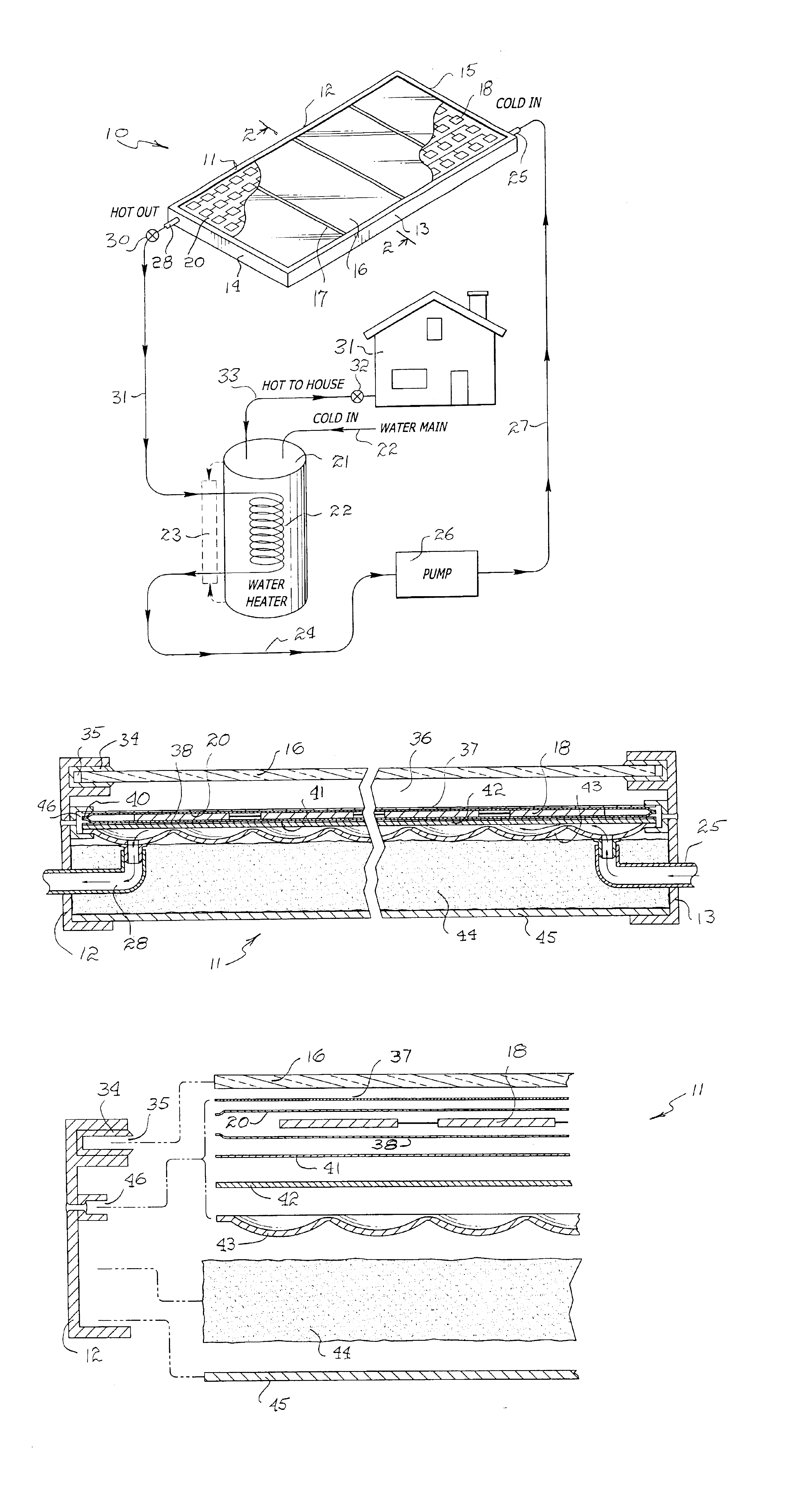
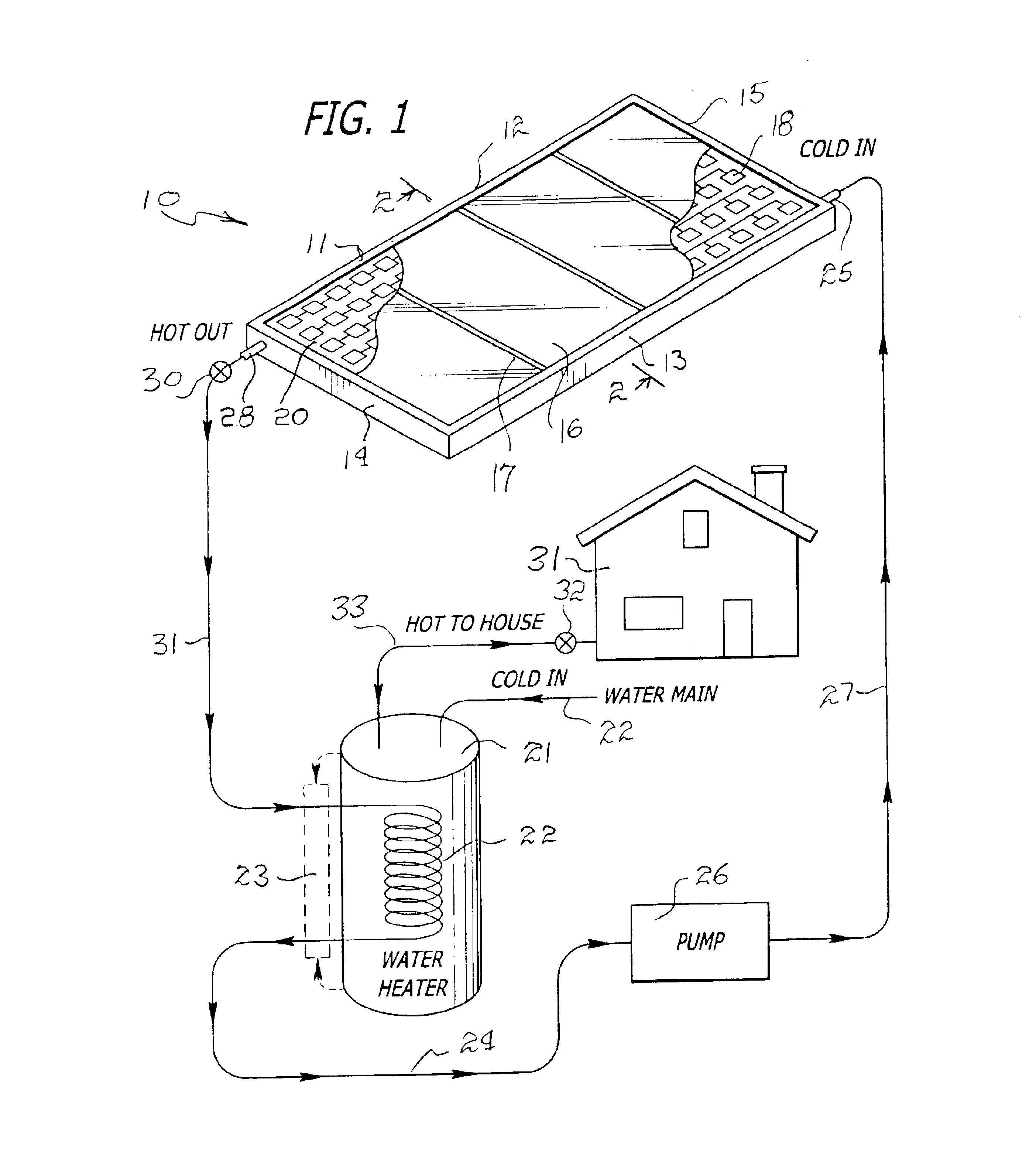
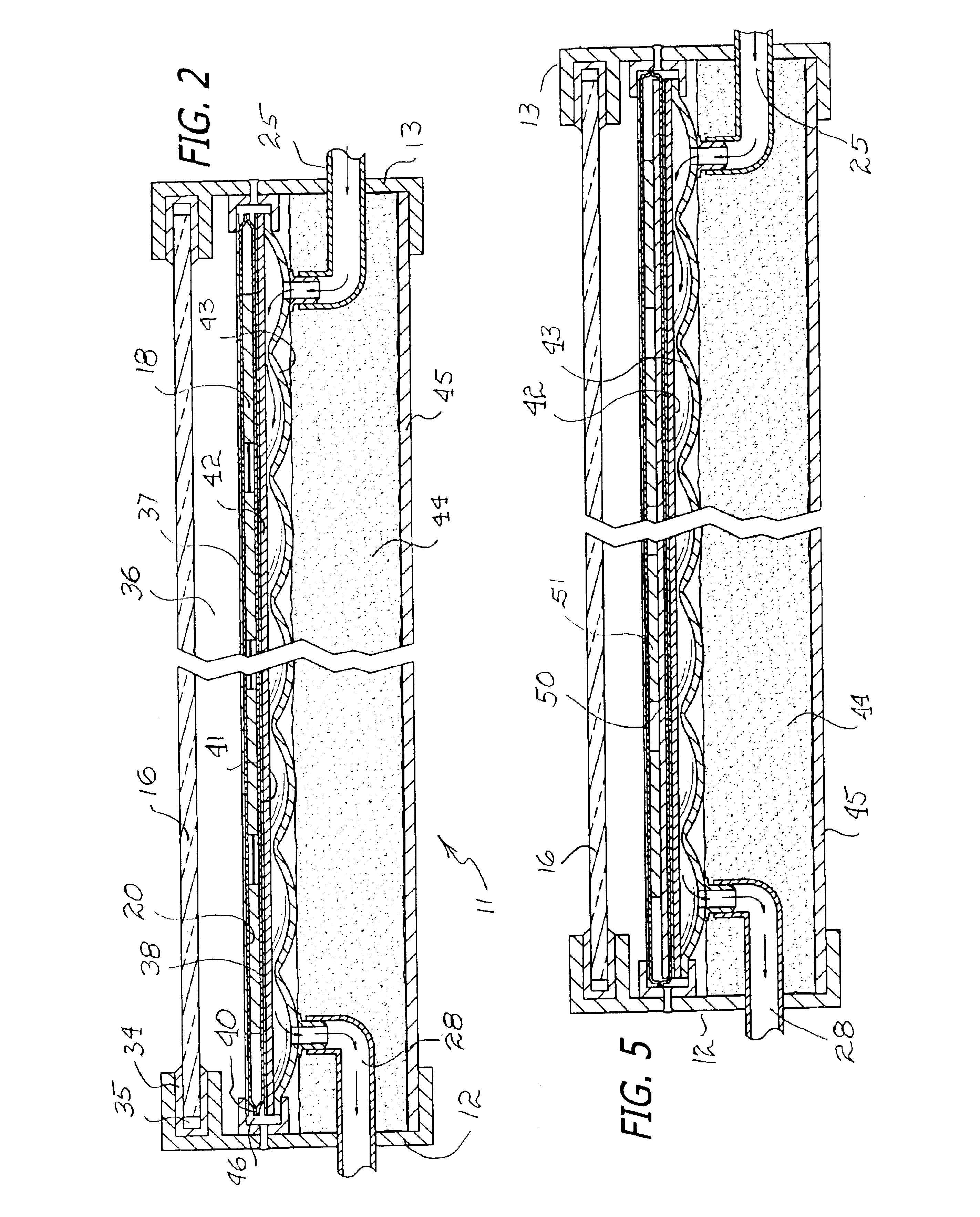
Referring to FIG. 1, the novel solar-powered heating system is illustrated in the general direction of arrow 10 which includes solar ray collection means and a fluid heating means included in a unitary assembly unit, indicated by numeral 11. The unit includes a framework having opposite sides 12 and 13 connected at their opposite ends to frame ends 14 and is respectively. The assembly 10 illustrates a plurality of glass panels, such as panel 16, arranged side-by-side between the opposite ends 14 and 15 and opposite sides 12 and 13. The adjacent edges of the glass panel 16 may be included in a mounting strip, such as strip 17, which connects the plurality of panels together in a flat arrangement. Immediately under the panels 16, there is provided an array of solar cells, such as cell 18, and it is understood that the cells may be connected in any suitable series, parallel or a combination thereof arrangement. In the embodiment shown in FIG. 1, the plurality of solar cells for collect...


PUM


Abstract

A solar-powered fluid heating system, having a thermal collector, a unitary water conducting assembly, and heat retention and efficiency components that are all included in a framework so as to provide a unitary construction. The framework includes a frame structure having non-conductive receptacles for receiving the edge marginal regions of the thermal conductor, so as to be free-floating to allow for thermal expansion and reduction of stresses on components as well as the heat resistant and enhancing components. The arrangement within the frame structure includes a dimpled or waffled metal water conducting assembly that rests upon a layer of insulation material held in the framing structure by a back sheet. The opposite side of the water conducting component is a solar selective sheet having a blackened surface upon which a thermal collector is disposed. The thermal collector includes an array of solar cells, deployed in either serial, parallel or a combination thereof, in an electrical array and which is encapsulated or enclosed by a pair of transparent sheets. A sheet of film is placed on top of the thermal collector, followed by a low glass panel arranged in fixed, spaced-apart relationship with respect to the film sheet. The edge marginal regions of all of the above components are carried in the side and ends of the frame structure and are held in position by spaced-apart, non-conductive receptacles for holding edge marginal regions of the components, and the receptacles are in spaced-apart relationship, so that the components are organized to be held in an augmenting and efficiency enhancing arrangement.

Description

BACKGROUND OF THE INVENTION1. Field of the InventionThe present invention relates to the field of solar-powered fluid heating systems, and more particularly to a novel solar-powered system having a thermal collector assembly which includes a novel fluid conducting structure, and which incorporates thermal conducting means having improved efficiency.2. Brief Description of the Prior ArtIn the past, it has been a conventional practice to employ commercially solar-powered water heating systems, which are self-contained in an unsealed enclosure which surrounds an array of photovoltaic cells for converting solar energy to a heated fluid, such as water or the like. Problems and difficulties have been encountered with such prior assemblies, such as that shown and described in U.S. Pat. No. 5,522,944. The problems and difficulties stem largely from the fact that many of the prior solar-powered water heating systems are unduly complicated, because the systems require an array of separate or ...

Claims


Application Information

Patent Timeline
IPC IPC(8): F24D17/00F24J2/04F24J2/20F24S10/50H01L31/058
CPCF24D17/0021F24J2/204H02S40/44Y02B10/20Y02E10/44Y02E10/60Y02B10/70F24S10/503Y02E10/50
Inventor LICHTENBERGER, MICHAEL
Owner LICHTENBERGER MICHAEL
Learn More