
Longitudinal coupled multiple mode surface acoustic wave filter

a surface acoustic wave and long-range coupled technology, applied in piezoelectric/electrostrictive/magnetostrictive devices, piezoelectric/electrostriction/magnetostriction machines, electrical equipment, etc., can solve problems such as fabrication difficulties

Inactive Publication Date: 2004-12-07
XENOGENIC DEV LLC
View PDF29 Cites 9 Cited by
  • Summary
  • Abstract
  • Description
  • Claims
  • Application Information

AI Technical Summary

Problems solved by technology

Consequently a space between the adjacent electrode fingers of the IDTs becomes narrow, resulting in difficulties in fabrication.

Method used


Image

  • Longitudinal coupled multiple mode surface acoustic wave filter
  • Longitudinal coupled multiple mode surface acoustic wave filter
  • Longitudinal coupled multiple mode surface acoustic wave filter

Examples


first embodiment

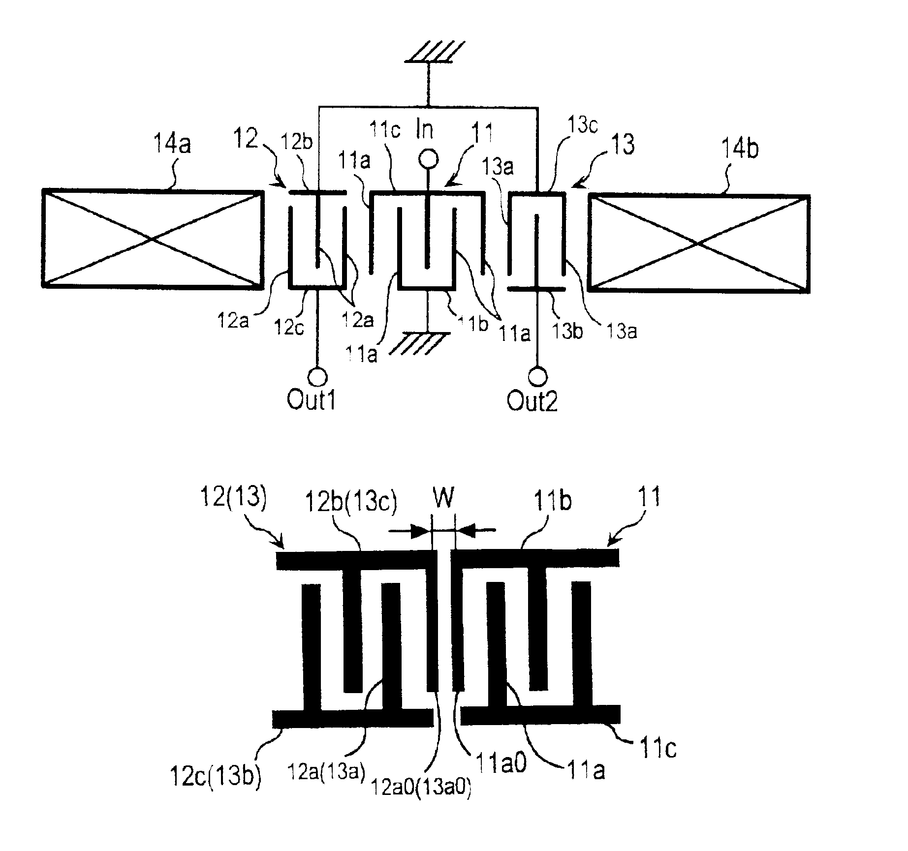
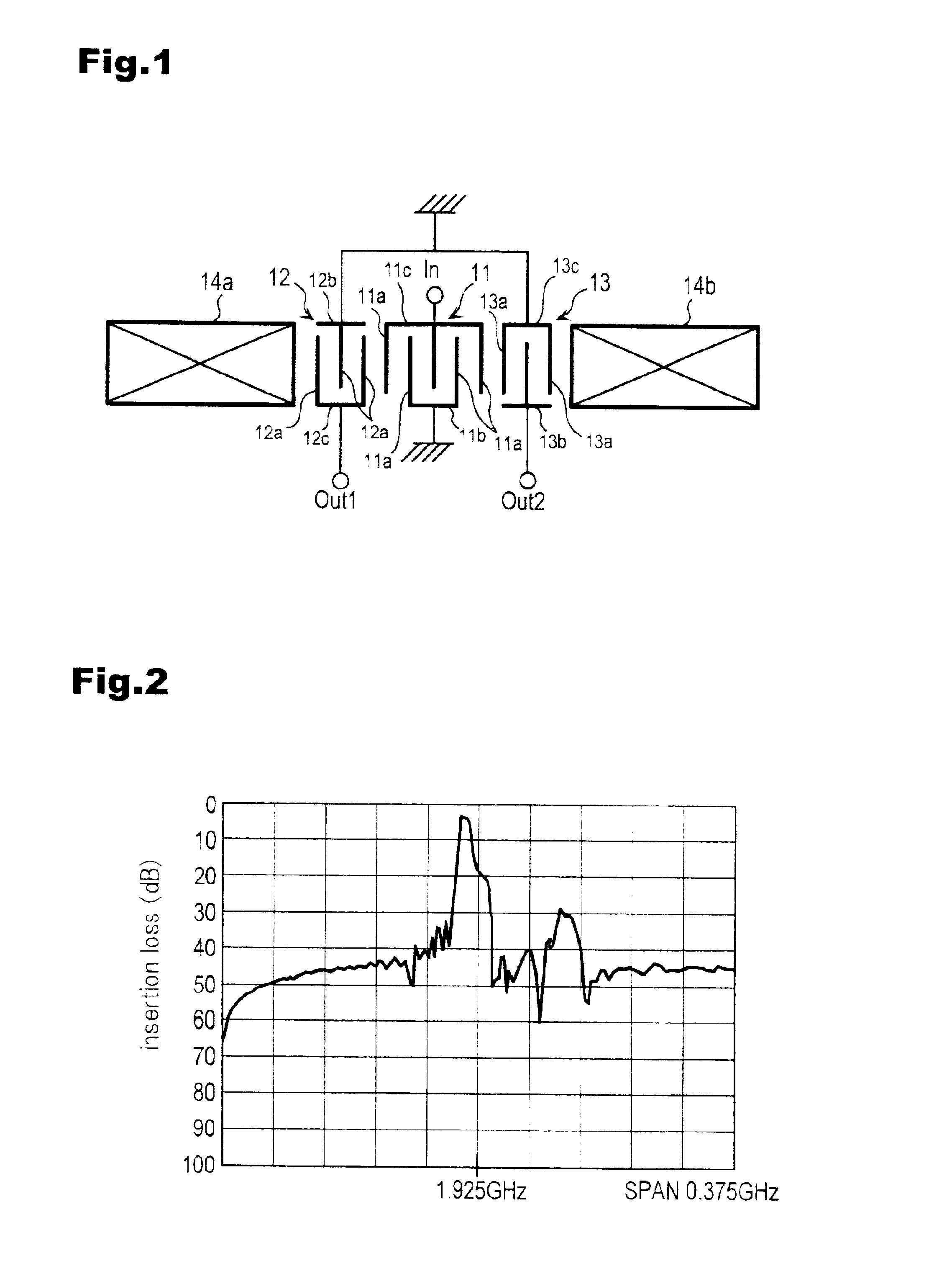
FIG. 1 is a schematic plan view illustrating a longitudinal coupled double mode SAW filter utilizing a longitudinal double mode according to the present invention.

The longitudinal coupled double mode SAW filter has an unbalanced input and balanced output configuration and comprises three IDTs 11, 12, 13 disposed closely to each other along a propagation direction of surface wave on a main surface of a piezoelectric substrate, and reflectors 14a and 14b disposed on both sides of the IDTs.

The IDTs 11, 12, 13 are respectively structured with comb electrodes 11b, 11c, 12b, 12c, 13b, 13c having a plurality of electrode fingers 11a, 12a, 13a, with each electrode finger inserted into a space of the other comb electrode. A comb electrode 11c of the middle IDT 11 is connected with an input terminal In and the other comb electrode 11b is grounded. A comb electrode 12b of the IDT 12 and a comb electrode 13c of the IDT 13 are mutually connected with each other and grounded. The other comb elect...

second embodiment

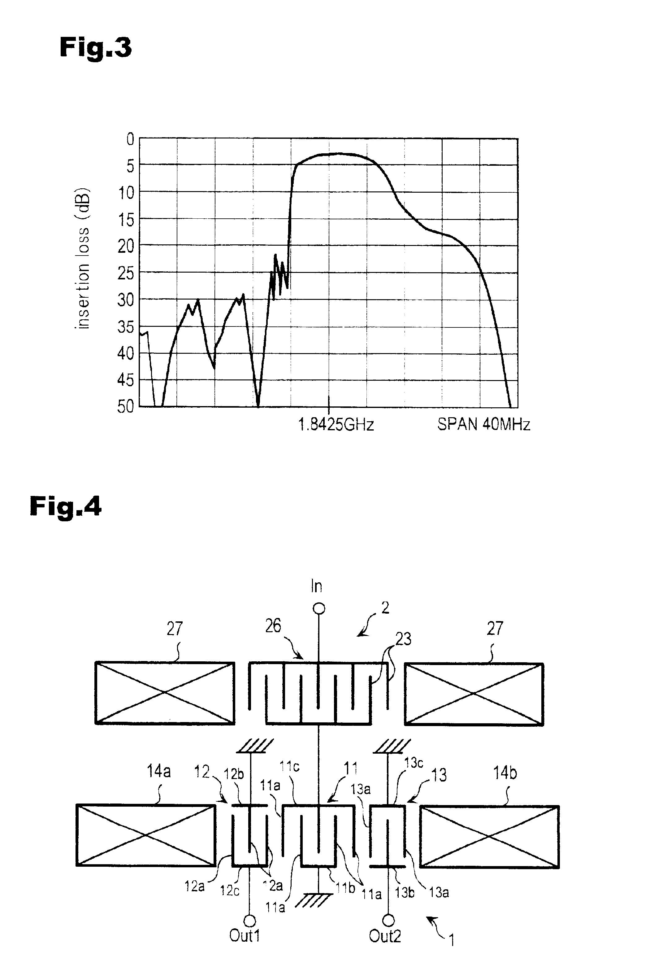
This second embodiment indicates the longitudinal coupled double mode SAW filter for a pass-band in a range between 1805 MHz and 1880 MHz. A horizontal axis of a graph in FIG. 6 indicates frequency (GHz), takes 1.925 GHz in its middle and is marked in 0.375 GHz increments. A vertical axis indicates an insertion loss and is marked in 10 dB decrements. FIG. 7 is a scaled-up graph indicating a value in the vicinity of the pass-band. A horizontal axis indicates a frequency (GHz), takes 1.8425 GHz in its middle and is marked in 40 MHz increment. A vertical axis indicates an insertion loss and is marked in 5 dB decrements.

As shown in FIGS. 6 and 7, the SAW filter in this embodiment demonstrates the superiority in attenuation at a low side and a high side of the pass-band over the SAW filter shown in FIG. 25. Also the SAW filter in this embodiment can obtain attenuation almost equivalent to that of an unbalanced and unbalanced type SAW filter shown in FIG. 24. As compared with FIGS. 2 and ...


PUM


Abstract

The present invention provides an unbalanced input and balanced output type SAW filter capable of obtaining stop-band attenuation approximately equivalent to that of an unbalanced input and unbalanced output type SAW filter. IDTs (12) (13) are respectively disposed on each side of a middle IDT (11). A comb electrode (11c) of the middle IDT (11) is connected with an input terminal (In) and other comb electrode (11b) is grounded. A comb electrode (12c) of the IDT (12) and a comb electrode (13b) of the IDT (13) are respectively connected with output terminals (Out 1) and (Out 2), and other comb electrode (12b) of the IDT (12) and other comb electrode (13c) of the IDT (13) are connected to each other and grounded. Electrode fingers (11a), (12a), (13a) of the middle IDT (11) and the side IDT (12), (13) are so arranged that adjacent electrode fingers of the middle IDT and the IDT on one side make a connection between terminals and the other adjacent electrode fingers of the middle IDT and the IDT on other side make a connection between a terminal and a ground.

Description

1. Field of the InventionThis invention relates to a surface acoustic wave filter (thereinafter to be referred to as an SAW filter).2. Description of Prior ArtAn SAW filter is a small and thin filter utilizing a surface acoustic wave and is in practical use as a key device for mobile communication equipments such as cellular phones. With the recent demands for a miniaturized, high-frequency cellular phone requiring low power consumption for a long-duration of call, there has been a growing demands for higher frequency SAW filters with lower insertion loss and higher power handling capability.FIG. 22 is a schematic plan view illustrating a longitudinal coupled double mode SAW filter utilizing a conventional primary-third order longitudinal mode. The SAW filter in FIG. 22 shows also an unbalanced input and unbalanced output type SAW filter. On a main surface of a piezoelectric substrate, as shown in FIG. 22, there are provided three IDTs (Interdigital Transducer) 61, 62, 63 closely di...

Claims


Application Information

Patent Timeline
Patent Type & Authority Patents(United States)
IPC IPC(8): H03H9/00H03H9/64
CPCH03H9/0038H03H9/6436H03H9/0042
Inventor TANAKA, NAOKIUSUKI, TATSURO
Owner XENOGENIC DEV LLC
Learn More