
Signature analysis registers for testing a computer graphics system

a technology of computer graphics and signature analysis, applied in the field ofgraphics systems, can solve the problems of increasing the complexity and amount of data being sent to the display device, affecting the display of images, and incorporating graphics processors with a great deal of processing power

Inactive Publication Date: 2004-11-16
ORACLE INT CORP
View PDF7 Cites 23 Cited by
  • Summary
  • Abstract
  • Description
  • Claims
  • Application Information

AI Technical Summary

Benefits of technology

"This patent is about a system and method for analyzing and detecting errors in graphics systems, particularly those with multiple display channels. The system uses a network of register to capture and accumulate data from the graphics system and compare it with a control signature to detect any hardware test failures. The technical effect of this patent is to provide a more efficient and effective way of testing and detecting errors in graphics systems, which can improve overall system performance and reliability."

Problems solved by technology

Modern graphics systems, however, incorporate graphics processors with a great deal of processing power.
This change is due to the recent increase in both the complexity and amount of data being sent to the display device.
Similarly, the images displayed are now more complex and may involve advanced techniques such as anti-aliasing and texture mapping.
As a result, without considerable processing power in the graphics system, the CPU would spend a great deal of time performing graphics calculations.
This could rob the computer system of the processing power needed for performing other tasks associated with program execution and thereby dramatically reduce overall system performance.
The increasing complexity of modern graphics systems places a burden on systems, personnel, and other resources involved with the testing of graphics systems and components.
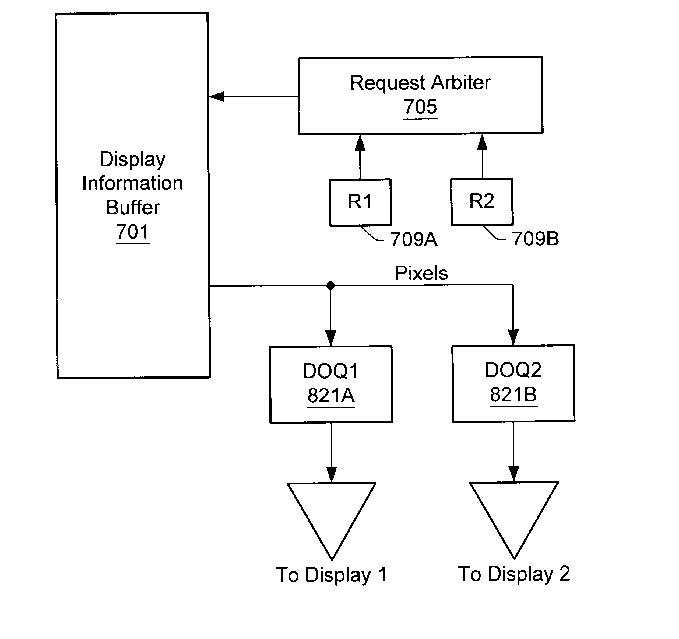
Additionally, graphics systems designed to support multiple streams of video with shared resources may make the task of system test unwieldy.
Differences between the accumulated signature and the control signature may indicate a hardware test failure.

Method used


Image

  • Signature analysis registers for testing a computer graphics system
  • Signature analysis registers for testing a computer graphics system
  • Signature analysis registers for testing a computer graphics system

Examples


Embodiment Construction

Computer System--FIG. 1

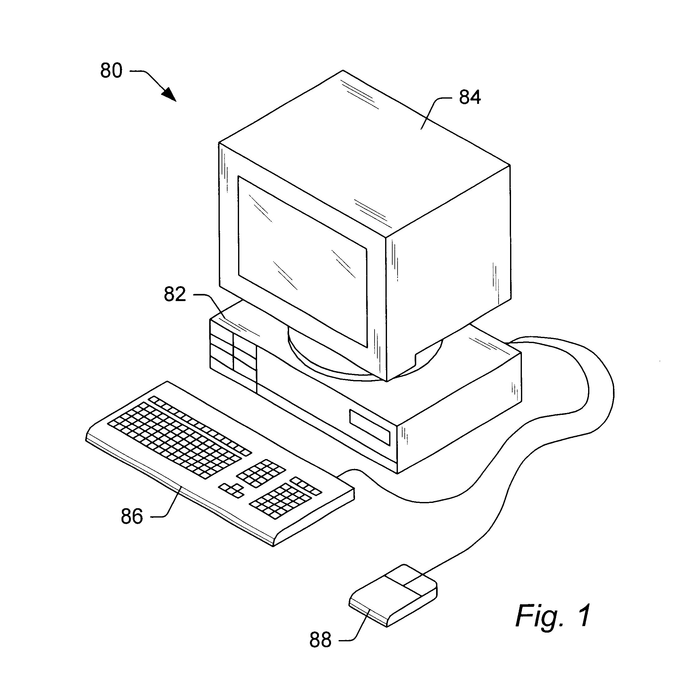
Referring now to FIG. 1, one embodiment of a computer system 80 that includes a graphics system is shown. The graphics system may be comprised in any of various systems, including a computer system, network PC, Internet appliance, a television, including HDTV systems and interactive television systems, personal digital assistants (PDAs), virtual reality systems, and other devices which display 2D and or 3D graphics, among others.

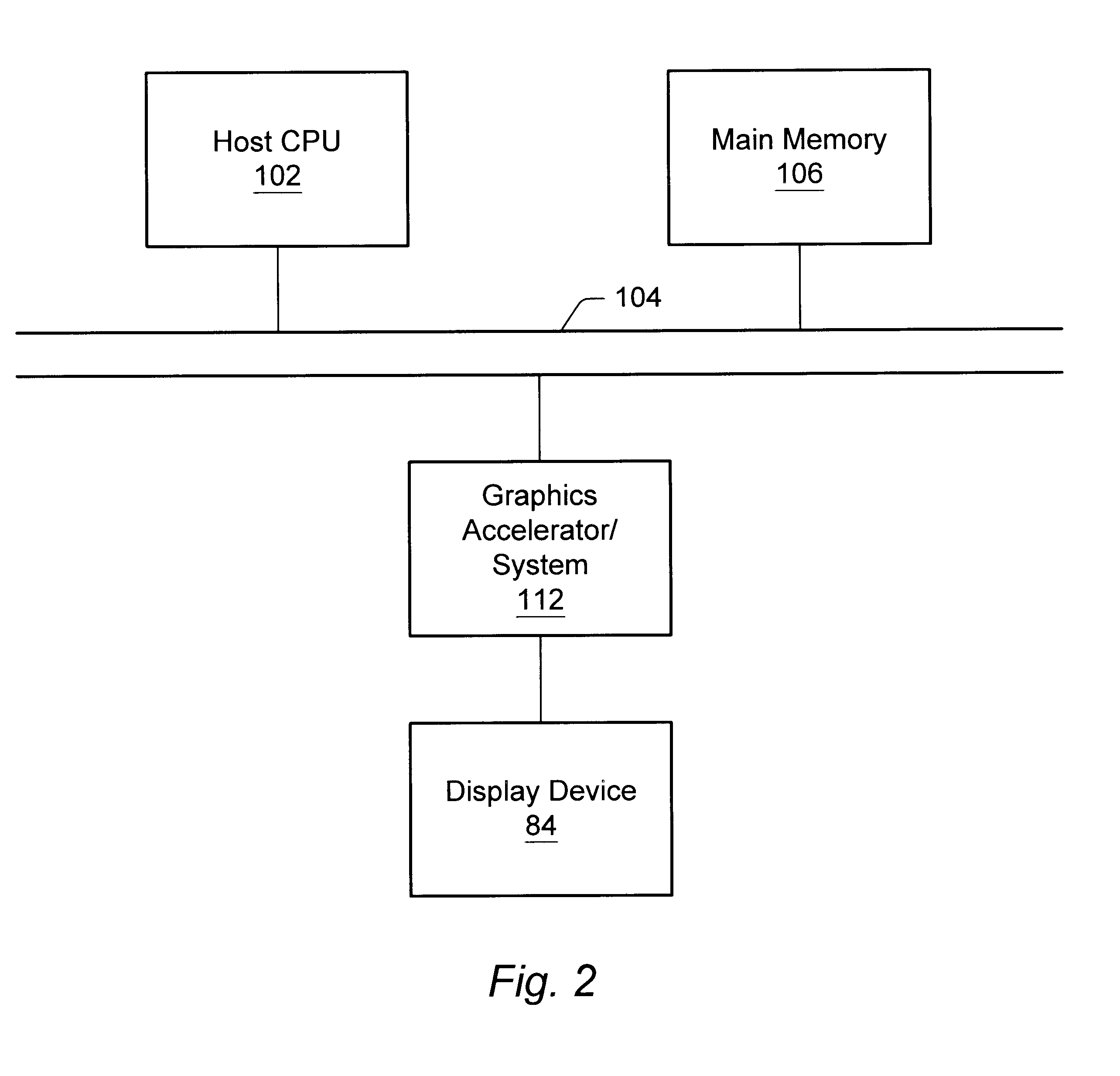
As shown, the computer system 80 comprises a system unit 82 and a video monitor or display device 84 coupled to the system unit 82. The display device 84 may be any of various types of display monitors or devices (e.g., a CRT, LCD, or gas-plasma display). Various input devices may be connected to the computer system, including a keyboard 86 and / or a mouse 88, or other input device (e.g., a trackball, digitizer, tablet, six-degree of freedom input device, head tracker, eye tracker, data glove, or body sensors). Application software may ...


PUM


Abstract

A signature capture and analysis system suitable for use in a high performance computer graphics system is described. The system employs a distributed network of signature analysis registers (SARs) which may be configured to capture and accumulate information from one or more channels of data over pre-defined periods of time. The SARs may be so distributed to allow for the isolation of faults to a sub-system level. The signature values developed in these SARs are, in some cases pre-seeded, and may include contributions from both data and control signals. Checking of the signature values against known good or expected outcomes is provided for. In some cases the SARs may be implemented as linear hybrid cellular automatons.

Description

1. Field of the InventionThis invention relates to graphics systems and, more particularly, to graphics systems capable of supporting multiple display streams or channels.2. Description of the Related ArtA computer system typically relies upon its graphics system for producing visual output on the computer screen or display device. Early graphics systems were only responsible for taking what the processor produced as output and displaying it on the screen. In essence, they acted as simple translators or interfaces. Modern graphics systems, however, incorporate graphics processors with a great deal of processing power. They now act more like coprocessors rather than simple translators. This change is due to the recent increase in both the complexity and amount of data being sent to the display device. For example, modern computer displays have many more pixels, greater color depth, and are able to display more complex images with higher refresh rates than earlier models. Similarly, t...

Claims


Application Information

Patent Timeline
Patent Type & Authority Patents(United States)
IPC IPC(8): G06F3/14G09G5/12G09G5/36
CPCG06F3/1431G09G5/001G09G5/363G09G5/12G09G2360/123G09G2330/12
Inventor WASSERMAN, MICHAEL A.YU, STEVEN TE-CHUNMAHAN, JUSTIN M.SCHIMPF, MICHAEL W.GRACON, GLENN
Owner ORACLE INT CORP
Learn More