
Sensor having electrode for determining the rate of flow of a fluid

a technology of fluid flow and sensor, applied in the field of sensors, can solve the problems of increasing the volume of sample required, variable flow rate, and increasing the dimensions of the flow path

Inactive Publication Date: 2004-10-05
ABBOTT LAB INC
View PDF22 Cites 474 Cited by
  • Summary
  • Abstract
  • Description
  • Claims
  • Application Information

AI Technical Summary

Benefits of technology

Enables precise and continuous monitoring of analyte concentrations in fluids with varying flow rates, improving the reliability and efficiency of biosensor systems by integrating flow rate measurement directly into the sensor design.

Problems solved by technology

Furthermore, healing or inflammation at the site of the body at which the interstitial fluid is collected during the course of operation of the biosensor can also result in variations in the rate of flow.
This additional device would have to be placed in the flow path of the sample, thereby causing an increase in the dimensions of the flow path, and hence, an increase the in the volume of sample required.
Moreover, an additional measurement system would be required, whereby the cost of the biosensor system would be increased.
A portion of this electrochemically active reaction product can diffuse back to the working electrode from the flow channel, thereby affecting the response of the biosensor.
If the duration of monitoring is too long, e.g., more than one hour, the reference voltage tends to drift over time.
As the voltage increases, other interfering agents will begin to contribute to the signal obtained.

Method used


Image

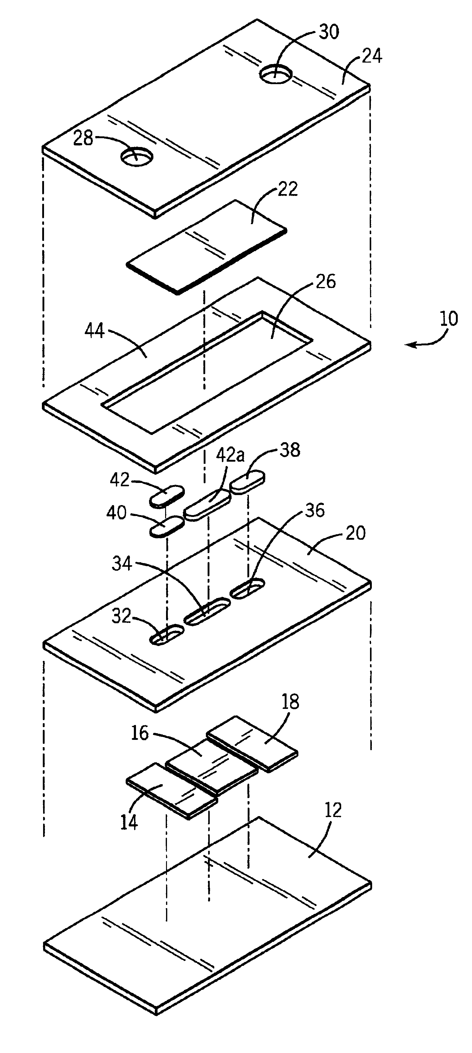
  • Sensor having electrode for determining the rate of flow of a fluid
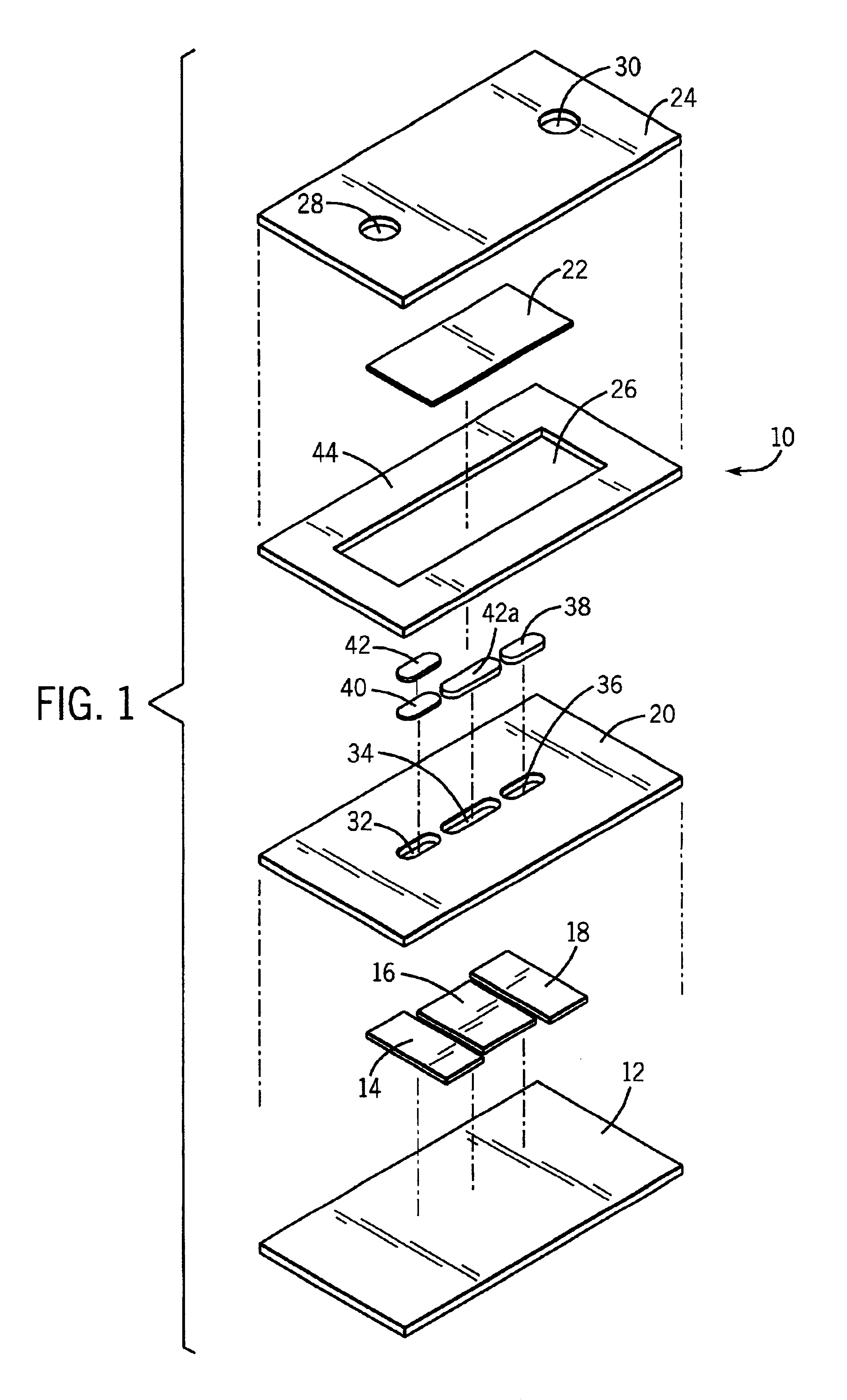
  • Sensor having electrode for determining the rate of flow of a fluid
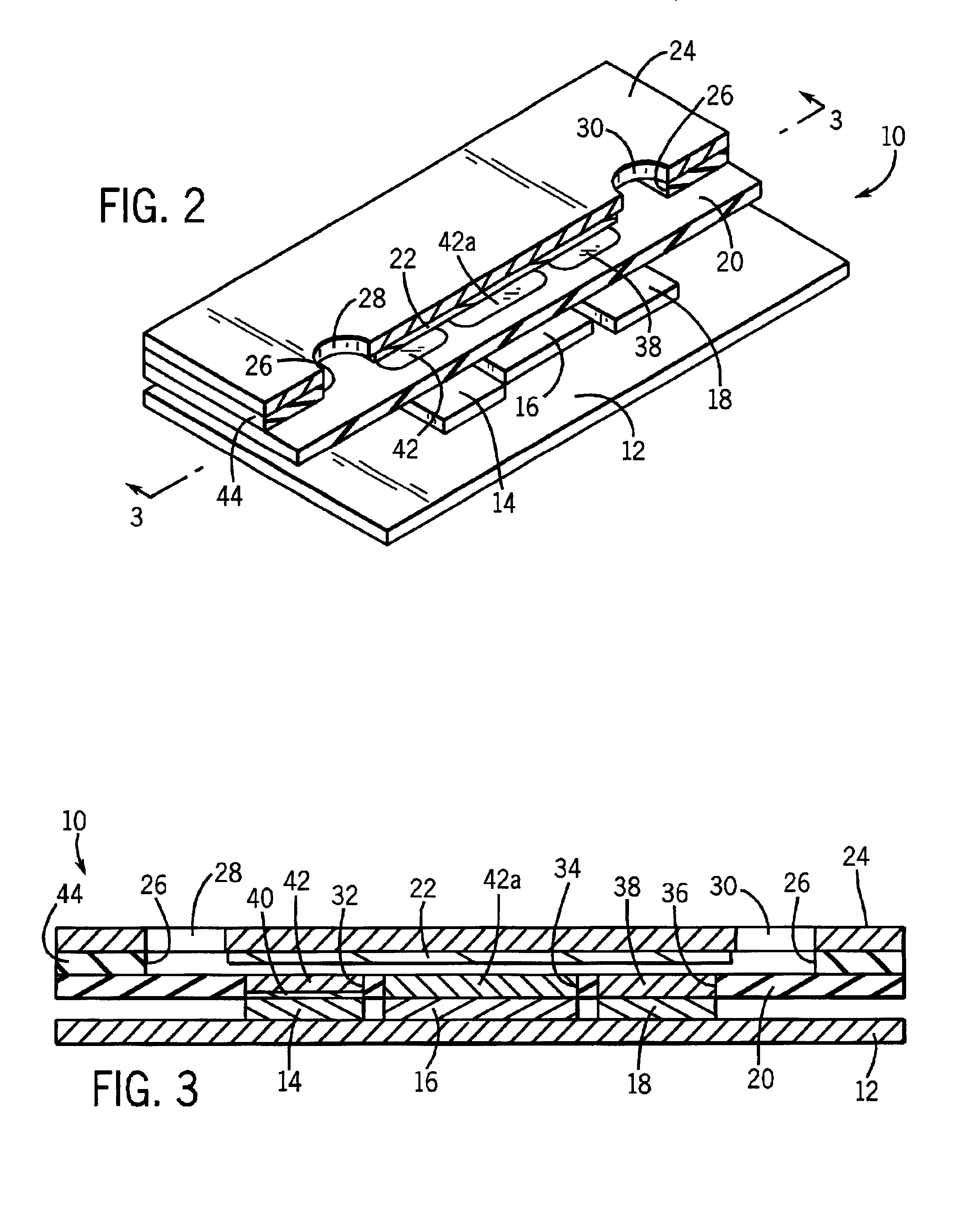
  • Sensor having electrode for determining the rate of flow of a fluid

Examples


example 1

This example illustrates a sensor suitable for monitoring the concentration of glucose in a biological sample with the additional capability of measuring the rate of flow of the biological sample. In this example, the working electrode is placed upstream of the flow rate-determining electrode. The sample passes over the working electrode before it contacts the flow rate-determining electrode.

The sensor comprises a working electrode made of platinum, a flow-rate determining electrode made of platinum, a reference electrode, and a counter electrode. Alternatively, the reference electrode and the counter electrode can be replaced by a dual-purpose electrode (i.e., counter / reference electrode) made of Ag / AgCl. The working electrode and the flow rate-determining electrode have deposited thereon a semi-permeable membrane to suppress interferences from electrochemically active interfering materials in the biological sample. Overlying the working electrode is a hydrogel membrane, which can ...

example 2

This example illustrates a sensor suitable for monitoring the concentration of glucose in a biological sample with the additional capability of measuring the rate of flow of the biological sample. In this example, the working electrode is placed upstream of the flow rate-determining electrode. The sample passes over the working electrode before it contacts the flow rate-determining electrode.

The sensor comprises a working electrode made of platinum, a flow-rate determining electrode made of platinum, a reference electrode, and a counter electrode. Alternatively, the reference electrode and the counter electrode can be replaced by a dual-purpose electrode (i.e., counter / reference electrode) made of Ag / AgCl. The working electrode and the flow rate-determining electrode have deposited thereon a semi-permeable membrane to suppress interferences from electrochemically active interfering materials in the biological sample. Overlying the working electrode is a hydrogel membrane, which can ...

example 3

This example illustrates a biosensor in which two flow rate-determining electrodes are used. The working electrode can be positioned such that the sample passes over a first flow-rate determining electrode prior to contacting the working electrode. After contacting the working electrode, the sample passes over a second flow rate-determining electrode.

The working electrode comprises the same materials and has substantially similar overlying layers as does the working electrode of Example 1. The flow rate-determining electrodes comprise the same materials and have the substantially similar overlying layers as do the flow rate-determining electrodes of Example 1. The counter electrode and the reference electrode comprise the same materials and have the substantially similar overlying layers as do the counter electrode and the reference electrode of Example 1.

In the embodiment of this example, both the flow rate and direction of flow of the sample can be determined. In order to perform ...


PUM

PropertyMeasurementUnit
depthaaaaaaaaaa
thicknessaaaaaaaaaa
thicknessaaaaaaaaaa

Abstract

Sensors that are capable measuring the rate of flow of a fluid that passes over the electrodes of the sensor. In these sensors, an electrode, designated the flow rate-determining electrode, is used in conjunction with the conventional electrodes, e.g., the working electrode, the reference electrode, and the counter electrode, to determine the rate of flow of the fluid. In one aspect, this invention provides a sensor for measuring the concentration of an analyte in a sample of fluid when the sample flows continuously over the electrodes of the sensor, especially when the rate of flow of the sample is relatively low. In another aspect, this invention provides a method for measuring the concentration of an analyte in a sample of fluid, wherein the rate of flow of the sample varies during the period of time that the sensor is in place. In a preferred embodiment, the sensor employs four electrodes, namely, a working electrode, a reference electrode, a counter electrode, and a flow rate-determining electrode. Alternatively, a single electrode that performs both the function of the reference electrode and the function of the counter electrode can replace the reference electrode and the counter electrode. In addition, a dummy electrode or a blank electrode can be used to compensate for interference from electrochemically active species. The reagent(s) specific to the analyte of interest is required to be deposited on the working electrode.

Description

BACKGROUND OF INVENTION1. Field of the InventionThis invention relates to sensors that are capable of determining the rate of flow of a fluid. More particularly, the sensors can be used to determine the concentration of an analyte in a sample of fluid in a continuous manner where the rate of flow of the sample of fluid is expected to vary during the determination.2. Discussion of the ArtDetermination of the rate of flow of a fluid is important in systems designed for chemical analysis of samples of fluid and delivery of chemicals such as drugs. When the rate of flow of a fluid is known, one can accurately determine the concentration of an analyte in the fluid, even if it is a slow-moving fluid, or the concentration of a chemical in a formulation being delivered from a reservoir.Certain sensors, known as continuous monitoring biosensors, can be used to continuously monitor the concentration of an analyte in a biological sample under either in vivo or in vitro conditions. For example,...

Claims


Application Information

Patent Timeline
Patent Type & Authority Patents(United States)
IPC IPC(8): C12Q1/00G01F1/56G01F1/64G01N27/26G01N27/28G01N27/327G01N27/416
CPCG01F1/64C12Q1/006
Inventor KARINKA, SHRIDHARA ALVAMOSER, ISABELLAJOBST, GERHARDTIETJEN, UWEPETROU, PANAGIOTA S.HERBERTH, UWEURBAN, GERALD
Owner ABBOTT LAB INC
Learn More