
Automated banking machine system and method

a technology of automatic banking machine and automatic banking, applied in the field of automatic banking machine system and method, can solve the problem of limiting the range of locations of atms

Inactive Publication Date: 2004-09-28
DIEBOLD SELF SERVICE SYST DIV OF DIEBOLD NIXDORF INC
View PDF6 Cites 92 Cited by
  • Summary
  • Abstract
  • Description
  • Claims
  • Application Information

AI Technical Summary

Benefits of technology

It is a further object of an exemplary form of the present invention to provide an automated banking machine that may be installed in locations which do not have land line based communication network connections and ports.
To reduce the possibility that wireless information may be intercepted by third parties, exemplary automated banking machines may be operative to perform a secure handshaking protocol with each portable wireless device. Such a protocol is operative to establish an encrypted communication channel for passing information between the banking machine and each portable wireless device. Such a protocol may be based on a Secure Sockets Layer (SSL) protocol for example which includes the authentication of digital certificates. Each automated banking machine, or a grouping of associated banking machines, may have their own digital certificates which can be independently authenticated by the portable wireless devices. Such digital certificates can provide the users of the portable wireless devices with assurances that the automated banking machine they are communicating with is a legitimate machine and not an imposter device posing as an automated banking machine for purposes of stealing account number information and identification values.

Problems solved by technology

Such land line based network requirements may limit the range of locations where an ATM can be installed.

Method used


Image

  • Automated banking machine system and method
  • Automated banking machine system and method
  • Automated banking machine system and method

Examples


Embodiment Construction

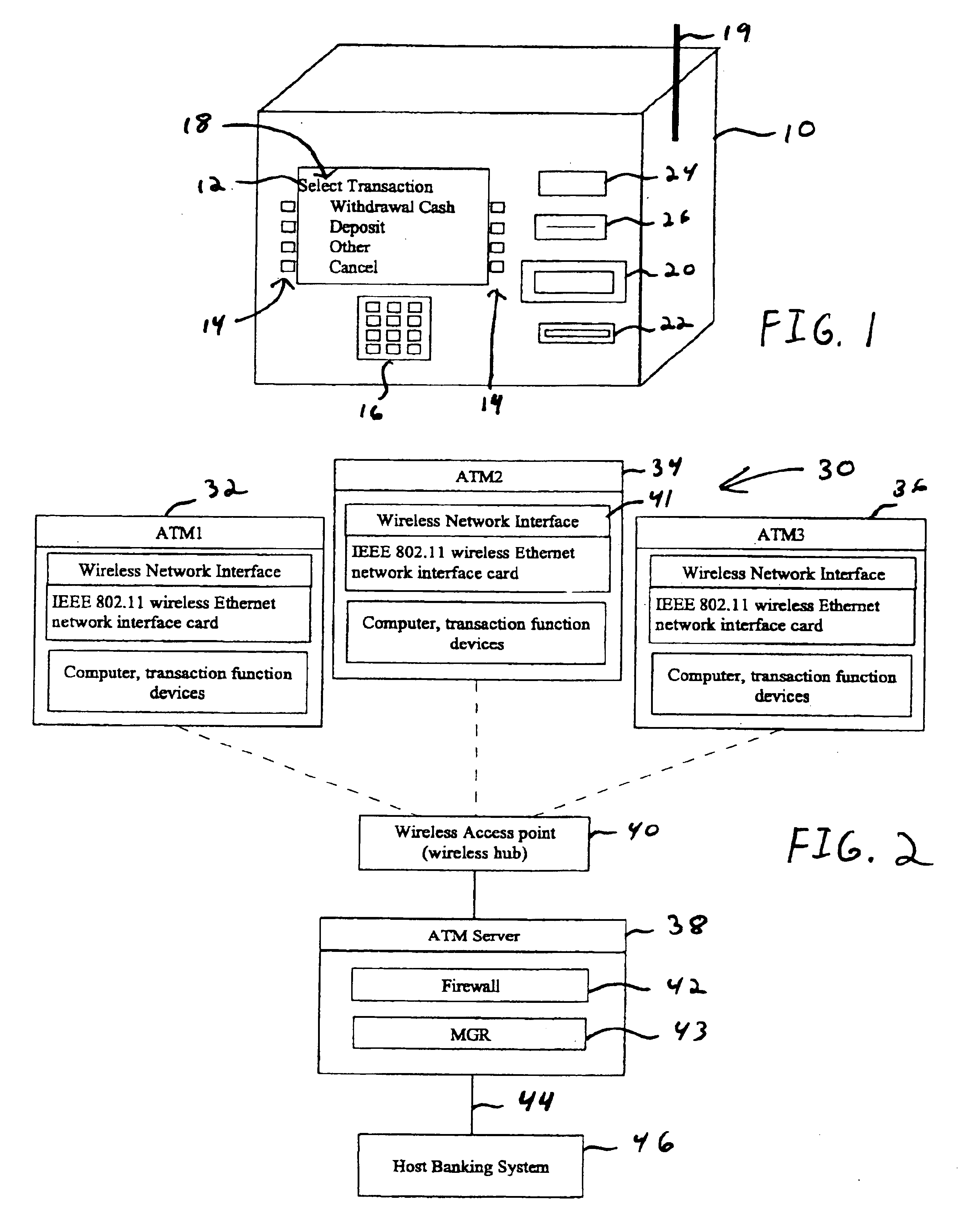
Referring now to the drawings and particularly to FIG. 1, there is shown therein a perspective view of an automated banking machine or ATM 10 of one exemplary embodiment of the present invention. The exemplary automated banking machine 10 includes at least one output device such as a display device 12. The output device 12 is operative to provide a consumer with a user interface 18 that includes a plurality of selectable options for operating the machine. The exemplary embodiment may further include other types of output devices such as speakers, or any other type of device that is capable of outputting visual, audible, or other sensory perceptible information.

The exemplary automated transaction machine 10 includes a plurality of input devices such as function keys 14 and a keypad 16. The exemplary embodiment may further include other types of input devices such as microphones or any other device that is operative to provide the machine with inputs representative of consumer communi...


PUM


Abstract

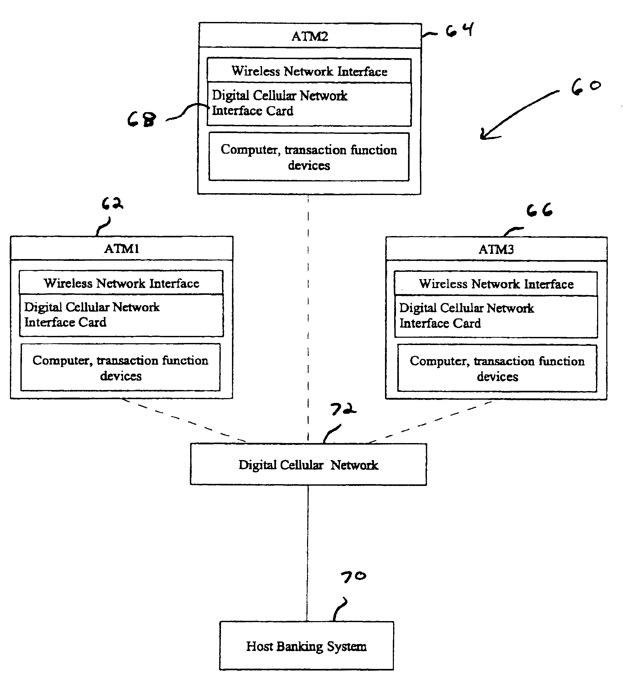
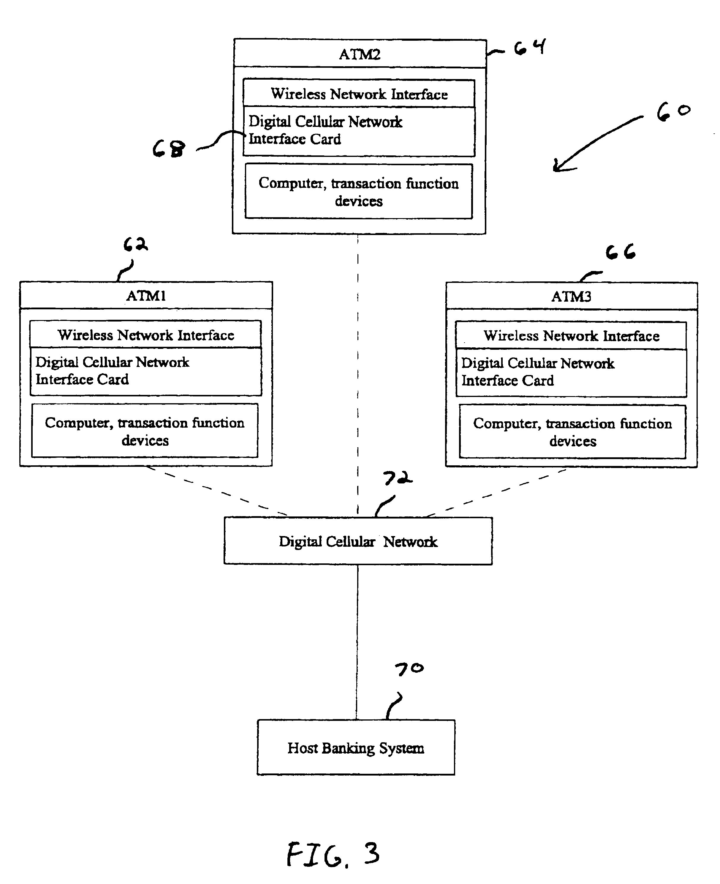
A wireless ATM system (30) comprises one or more wireless ATMs (32, 34, 36) that are operative to wirelessly communicate with a wireless ATM server (38). The wireless ATMs each include a wireless network interface (41). The wireless ATM server includes a corresponding wireless access point or wireless hub (40). Wireless transmission between the wireless ATMs and wireless ATM server is secured with a wireless encryption protocol. The wireless ATM server is operative to communicate with at least one host banking system (46) through at least one public or private network (44). The wireless ATM server is operative to route transaction and event messages between the host banking system and each of the wireless ATMs using a message gateway router (43). The wireless ATM server further includes a firewall (42).

Description

This invention relates to automated banking machines. Specifically this invention relates to an automated banking machine system and method that includes operating an automated banking machine with a portable device in a secure wireless network environment.Automated banking machines are known. A type of automated banking machine used by consumers is an automated teller machine ("ATM"). ATMs enable customers to carry out banking transactions. Banking transactions that may be carried out with ATMs may include the dispensing of cash, the receipt of deposits, the transfer of funds between accounts, the payment of bills, cashing checks, receiving money orders and account balance inquiries. The type of banking transactions a customer can carry out are often determined by the capabilities of the particular banking machine and the programming of the machine by the institution operating the machine. Other types of automated banking machines may allow customers to charge against accounts or t...

Claims


Application Information

Patent Timeline
IPC IPC(8): G06Q20/00G07F19/00G06Q20/32
CPCG06Q20/32G06Q20/3223G07F19/20G07F19/211G06Q20/1085
Inventor DRUMMOND, JAY PAULSMITH, MARK D.
Owner DIEBOLD SELF SERVICE SYST DIV OF DIEBOLD NIXDORF INC
Learn More