
Navigation device

a technology of navigation device and compass, which is applied in the direction of educational appliances, instruments, and ways, and can solve problems such as some burden

Inactive Publication Date: 2004-09-28
PRIESCHL MARCO
View PDF10 Cites 3 Cited by
  • Summary
  • Abstract
  • Description
  • Claims
  • Application Information

AI Technical Summary

Benefits of technology

The compass module may be designed according to one of several embodiments including a first embodiment using an elongate neodymium or samarium cobalt permanent magnet and a ferrofluid. A ferrofluid is a fluid that can be manipulated by a magnetic field. The ferrofluid used in the compass module is a stable, colloidal suspension of nano-sized particles in a liquid carrier, the particles being coated with a surfactant to prevent agglomeration. In the presence of a magnetic field, the magnetic moments of the particles align themselves with the field lines, allowing the fluid to behave as a homogenous liquid. The magnetic field also increases the density of the fluid. When applied to the magnet, the fluid forms beads at opposite ends of the magnet, which beads support the magnet as a low friction bearing and also act as a damper to minimize oscillations.

Problems solved by technology

While the foregoing procedure might be considered great fin by someone on an orienteering expedition in a remote area, it is somewhat burdensome for a tourist in an urban area, who typically is not armed with a compass and may not know how to use one anyhow.
Such a device would also be useful for someone already familiar with a city, since emerging from an unfamiliar subway station can be disorienting.

Method used


Image

  • Navigation device
  • Navigation device
  • Navigation device

Examples


Embodiment Construction

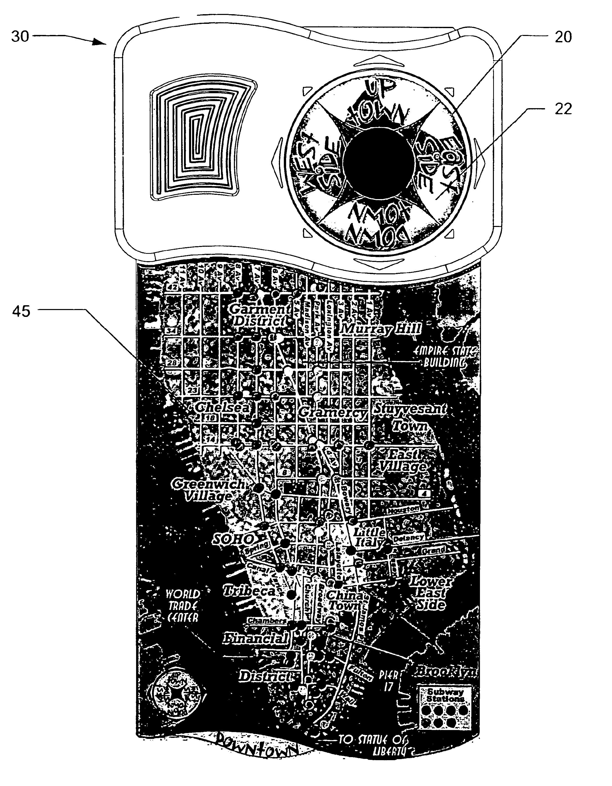
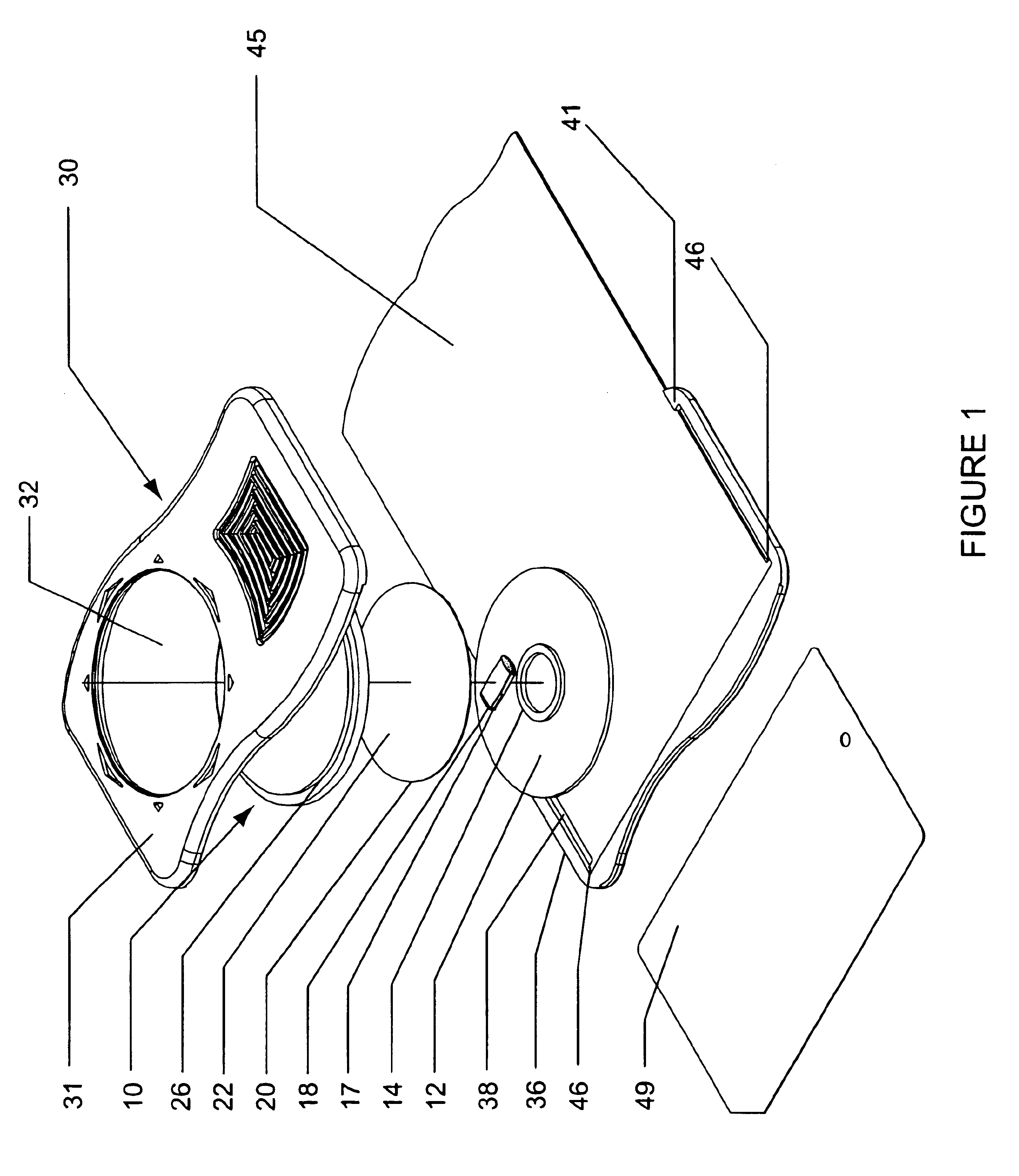
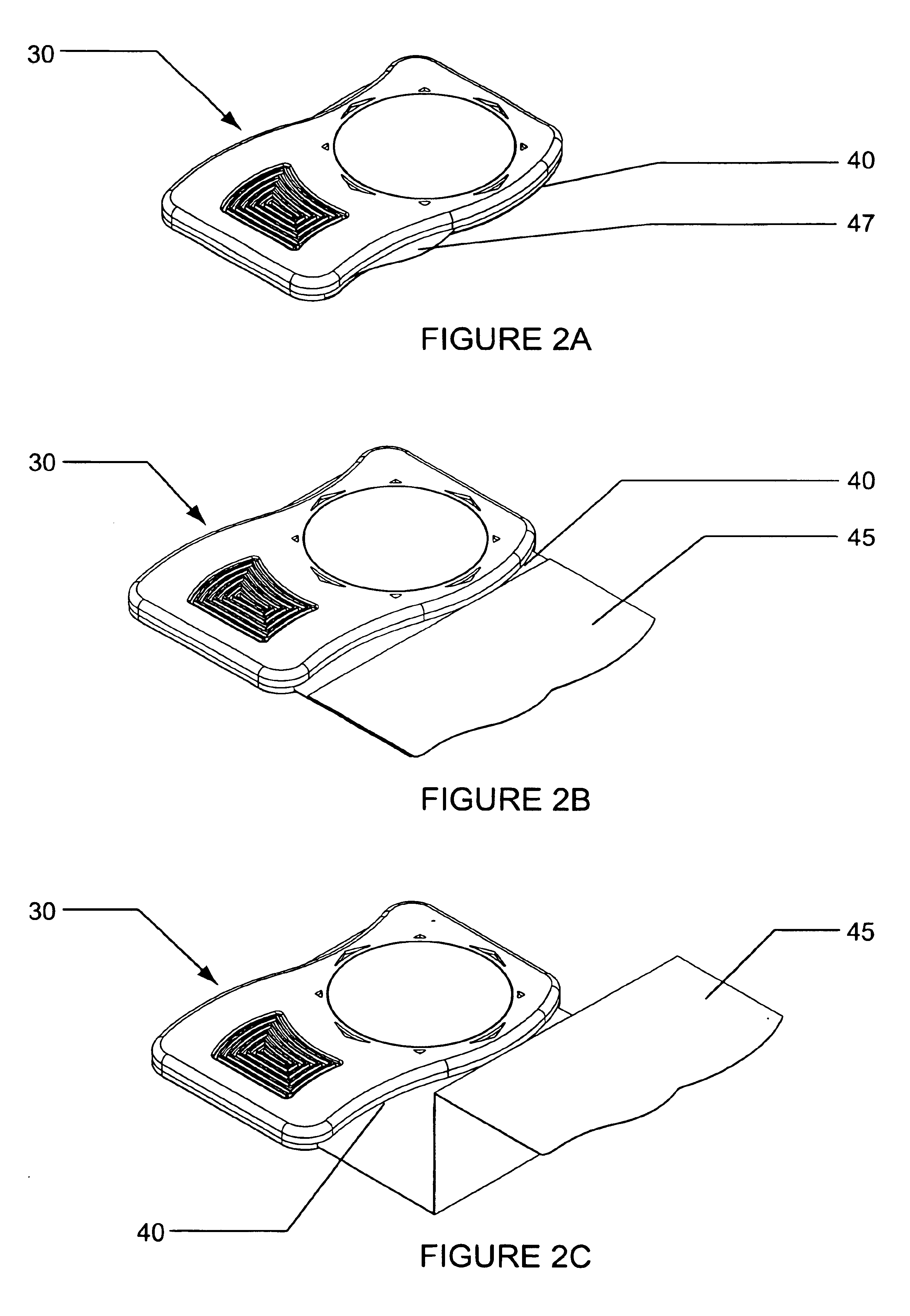
Referring to FIG. 1, the navigation device according to the invention includes a compass module 10, a housing 30 in two parts 31, 36, and a map 45. While not part of the device, a transit card 49 may also be stored in the housing, as will be described.

Referring also to FIG. 6, a first embodiment of compass module 10 includes a base 12 having a collar 14 which receives an elongate dipolar permanent magnet 17 having ferrofluid beads 18 adhering to polar opposite ends of the magnet by magnetic attraction. The magnet 17 is preferably neodymium, which exerts a magnetic force many times that of a conventional ferrous magnet, thus enabling a very small size, e.g. on the order of one centimeter in length. A disc 20 is adhered to the top of the magnet, the top of the disc having a surface 22 which bears map indicia, as will be described. A transparent cover 26 is fitted to the base 12 in a snap fit, the cover 26 having an inner circumferential lip 27 which snaps over the edge 15 of the base....


PUM


Abstract

The navigation device includes a compass module including a base, a permanent dipolar magnet mounted for rotation relative to the base so that the magnet tends to align with the earth's magnetic north, a disc having a display fixed with respect to the magnet, and a transparent cover fixed to the base and arranged over the display surface. The display surface has map indicia for a pre-determined geographic area, map indicia being oriented to define a direction of magnetic north with respect to the map indicia, the indicia being aligned with respect to magnet so that the direction of magnetic north with respect to the map indicia coincides with earth's magnetic north when the magnet is aligned with earth's magnetic north. The compass module is fixed in a housing having a slot from which a folded map of the pre-determined area can be withdrawn, one end of the map remaining fixed to the housing. When the user rotates the map so that indicia on the disc are parallel to corresponding indicia on the map, the user will be correctly oriented to features on the map.

Description

1. Field of the InventionThe present invention relates to a navigation device which is adapted for use in a pre-determined geographic area. More particularly, the invention relates to a navigation device using a magnet which is free to rotate so that it can align with the earth's magnetic field.2. Description of the Related ArtA conventional compass usually includes a magnetic needle which is mounted for rotation over a face indicating the principal directions of north, south, east and west at ninety degree intervals, and may include gradations therebetween for precise determination of a traveler's direction or bearing. The needle is typically journaled on a pin fixed in a housing having a transparent cover for viewing the position of the needle relative to the compass face, whereby the user can determine which way is north. When a user wishes to orient himself with respect to features on a map, the map must be oriented with respect to the compass, so that the north point on the map...

Claims


Application Information

Patent Timeline
Patent Type & Authority Patents(United States)
IPC IPC(8): G01C17/00G01C17/04G09B29/10
CPCG01C17/04G09B29/106
Inventor PRIESCHL, MARCO
Owner PRIESCHL MARCO
Learn More