
Tarpaulin deployment device

Inactive Publication Date: 2004-09-07
CON WAL
View PDF20 Cites 6 Cited by
  • Summary
  • Abstract
  • Description
  • Claims
  • Application Information

AI Technical Summary

Benefits of technology

The devices represented by the prior art fail to effectively deploy and take up cost effective alternative daily cover in a simplified, inexpensive, easy to use manner. The invention disclosed is an improvement over the prior art in that it allows for the use of inexpensive, reusable tarpaulins, it employs a simplified, inexpensive spindle and tarpaulin component to carry and deploy the alternative daily cover that can be used at small landfills with a minimum of labor, it employs weight-saving design features so that it can be used with smaller, less expensive machinery, and it is less likely to cause deploying devices to sink into and become mired in the waste materials which constitute a landfill than the heavier devices disclosed by the prior art.
In one aspect, the invention is directed to a component of a device used to deploy and take up a tarpaulin, to be used primarily in the field of waste management and specifically to assist in the use of a tarpaulin as a reusable, inexpensive alternative daily cover for landfills. The device comprises a spindle and a tarpaulin, wherein the tarpaulin is contained on and secured to the spindle. The device is intended to be used with a deployment device, which typically is lifted and positioned by the use of heavy equipment typically used at landfills, such as bulldozers, compactors, and excavators. The device employs weight-reducing design features which permit it to be used with smaller positioning equipment.
This aspect of the invention may include one or more of the following features: the spindle may be hollow for reduced weight and may have both interior and exterior reinforcing components for increased strength, and the tarpaulin may include a narrow tongue which serves as a connection point to the spindle, thereby allowing use of a tarpaulin having a width greater than the length of the spindle.

Problems solved by technology

However, the use of that amount of cover soil on a daily basis is expensive and takes up an unacceptable amount of valuable landfill air space, thereby reducing the capacity of a landfill and shortening its useful life.
However, this device suffers from the disadvantage of its reliance on the thin film material.
This feature adds significantly to the complexity and weight of the device.
Moreover, the heavy equipment used to position the device is also used to provide power to the hoppers and must be modified somewhat to accommodate attachment to the device, resulting in downtime between use of the equipment with the device and for other purposes.
Because of the reliance of the device on the use of light weight thin film, it cannot accommodate heavier, but far less expensive, alternative daily covers, such as reusable tarpaulins.
Also, the increased weight of the device due to the need to employ hoppers makes the device impractical for use with landfills having unusually soft or wet content.
Reusable tarpaulins are an effective, low-cost alternative daily cover, but can be difficult to deploy and take up because of their bulk and weight.
The deployment process is labor intensive and dangerous if done by hand.
Simply dragging a tarpaulin with a machine can be destructive to the tarpaulin.
However, this device employs a complicated means for attaching and detaching the spindle about which is wrapped the tarpaulin, as well as means for raising and lowering an attached spindle with respect to the framework.
As such, it represents a fairly complicated, expensive solution to the problem of deploying reusable, cost effective alternative daily cover.
The devices represented by the prior art fail to effectively deploy and take up cost effective alternative daily cover in a simplified, inexpensive, easy to use manner.

Method used


Image

  • Tarpaulin deployment device
  • Tarpaulin deployment device
  • Tarpaulin deployment device

Examples


Embodiment Construction

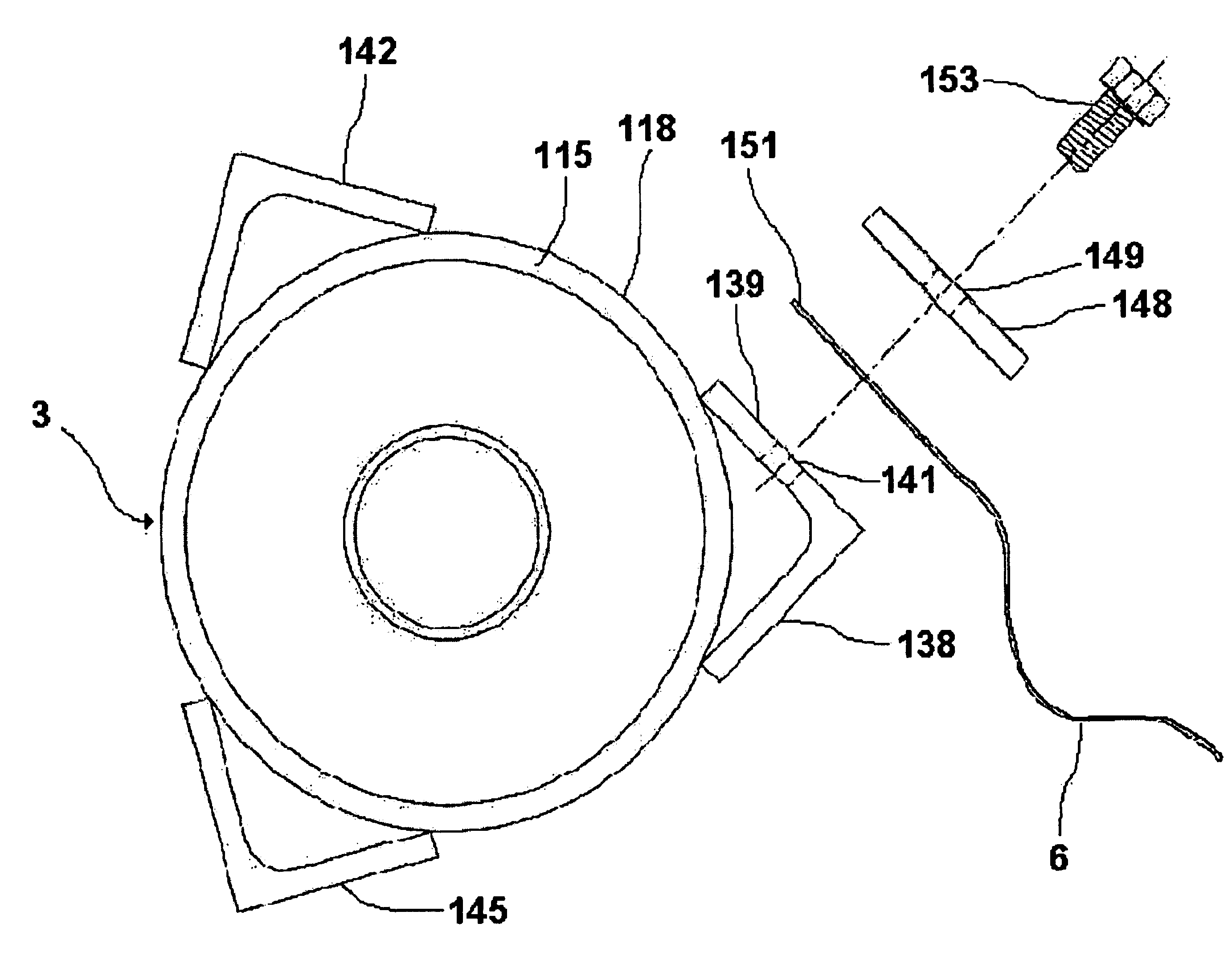
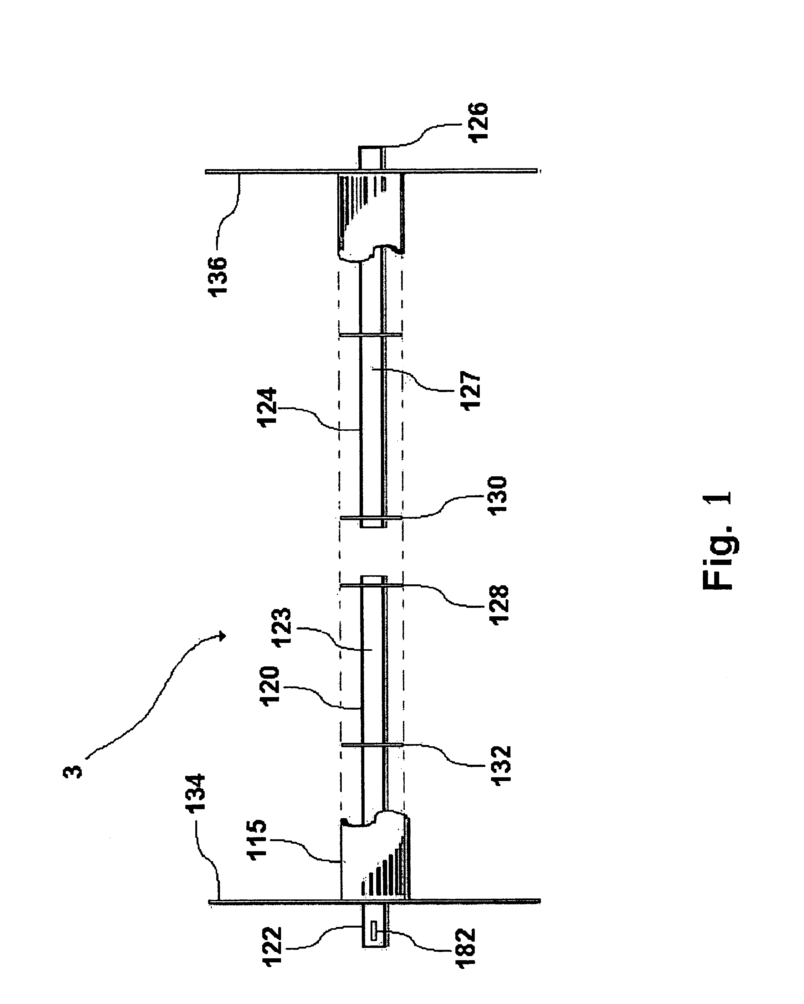
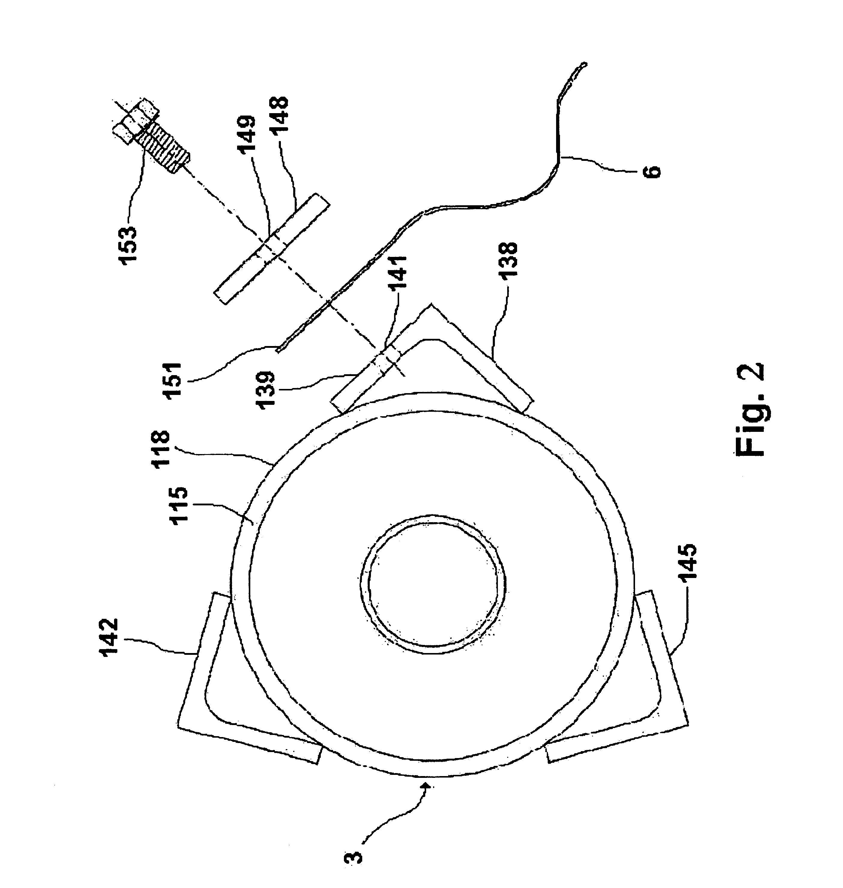
FIG. 1 shows a cut away side view of one embodiment of the spindle 3. The spindle 3 is used to take up and deploy the tarpaulin 6. The spindle 3 is comprised of a spindle casing 115, a first spindle axle 120, and a second spindle axle 124. In one embodiment the spindle 3 also employs reinforcement disks 128,130,132. The spindle casing 115 is a cylindrical hollow metal tube having a constant inside diameter. The first spindle axle 120 is a solid metal rod having a round cross-section and a constant diameter. Its overall length is less than one half the length of the spindle casing 115. The second spindle axle 124 is a solid metal rod having a round cross-section and a constant diameter substantially equal to the diameter of the first spindle axle 120 and having a length less than one half the length of the spindle casing 115. The outside end 122 of the first spindle axle 120 or the outside end 126 of the second spindle axle 124 may include a slot 182 or other means for assisting with...


PUM


Abstract

An improved spindle and tarpaulin combination to be used in devices to deploy and take up a tarpaulin. The device is comprised of a reinforced spindle and a tarpaulin adapted to be attached to the spindle, such that the tarpaulin may be wound and unwound upon the spindle, with the tarpaulin adapted for use with a spindle having a length substantially less than the width of the tarpaulin.

Description

1. Technical FieldThe invention relates generally to the field of solid waste management and is directed to a combination device useful as a component in devices used for deploying and taking up a reusable cover for the open face of a landfill. More specifically, the invention is directed to an improved tarpaulin and spindle combination designed to be light weight, easily movable by typical landfill heavy equipment, and suitable for providing alternate daily cover in an inexpensive manner.2. Description of Prior ArtPursuant to federal regulation, all sanitary landfills are required to have their working faces covered at the end of each day or when not being worked in order to control disease, fires, odors, blowing litter, and scavenging. The traditional daily cover used is soil, at a minimum required depth of six inches. However, the use of that amount of cover soil on a daily basis is expensive and takes up an unacceptable amount of valuable landfill air space, thereby reducing the...

Claims


Application Information

Patent Timeline
IPC IPC(8): A01G13/02B09C1/00
CPCA01G13/0287B09C1/005Y10S411/911
Inventor PITCHER, TERRY
Owner CON WAL
Learn More