LAN relaying/switching apparatus

a relaying/switching apparatus and relay technology, applied in the field of relaying/switching apparatuses, can solve the problems of suppressing the amount of data flow, and the inability to selectively suppress the transmission of data

Inactive Publication Date: 2004-08-31
FUJITSU LTD
View PDF10 Cites 25 Cited by
  • Summary
  • Abstract
  • Description
  • Claims
  • Application Information

AI Technical Summary

Problems solved by technology

Therefore, it is impossible to selectively suppress the transmission of the data from the apparatus transmitting the data causing the overflow state 3.
Namely, the controller transmits the RM cell which limits the band of the specific data flow from the ATM terminal portions to the apparatus transmitting the date flow causing a jam, thereby suppressing the data flow amount.

Method used


Image

  • LAN relaying/switching apparatus
  • LAN relaying/switching apparatus
  • LAN relaying/switching apparatus

Examples


Embodiment Construction

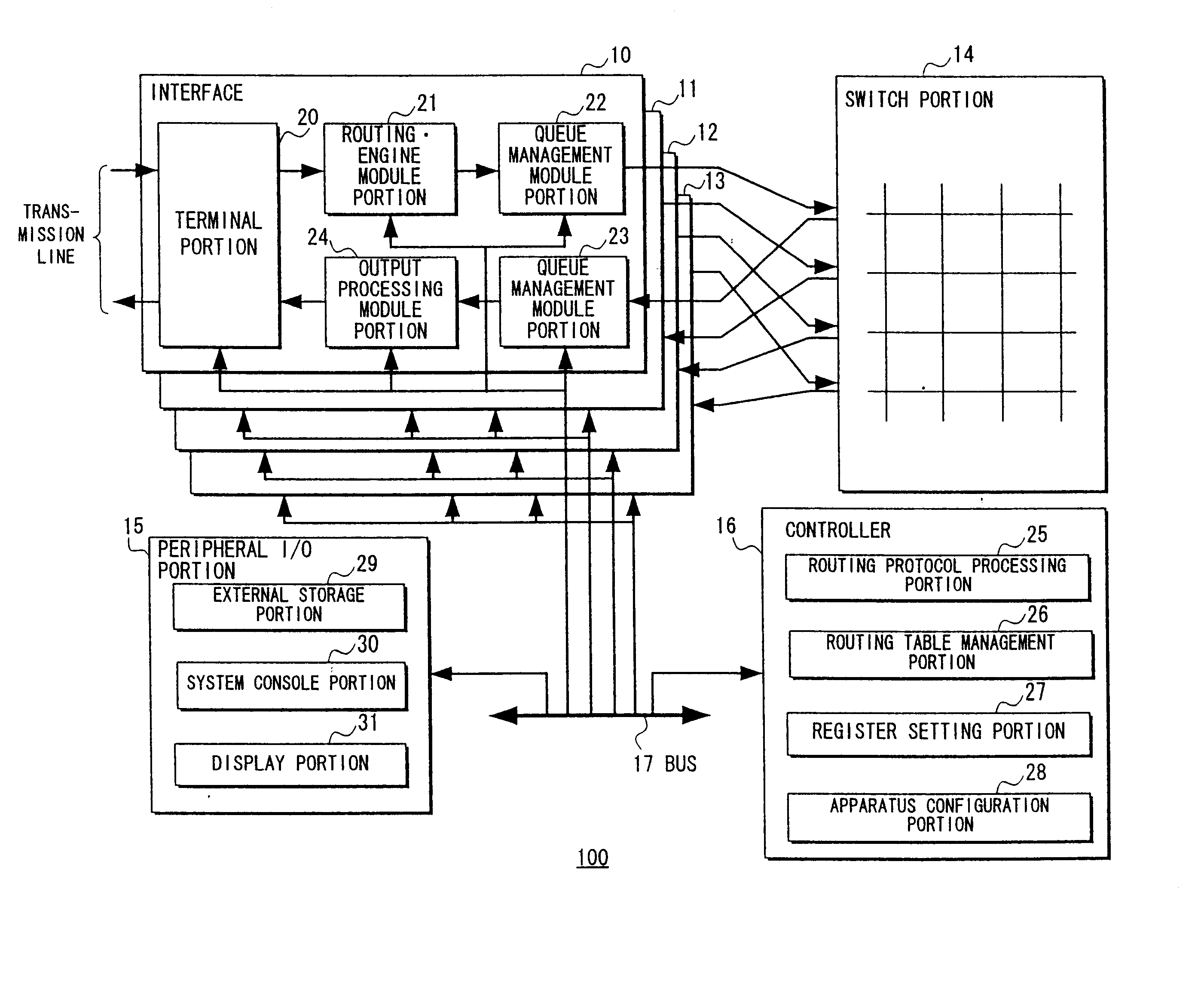
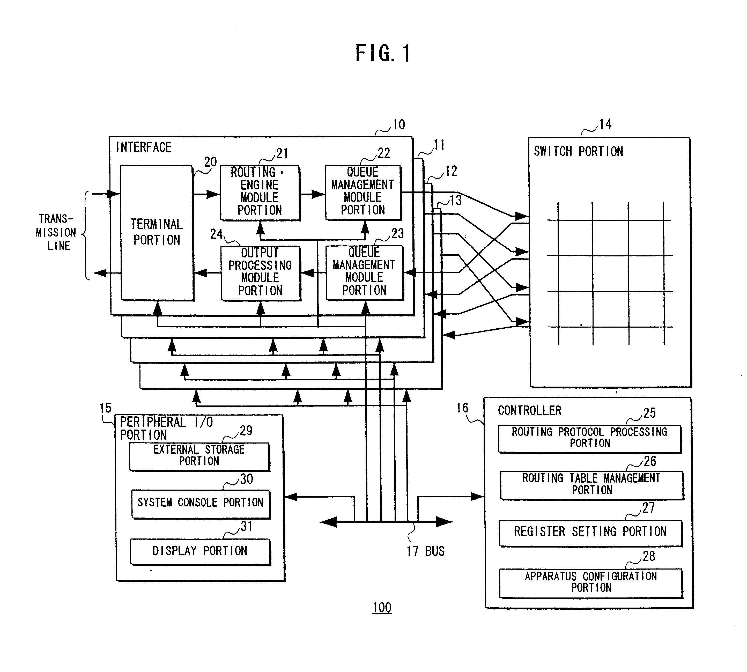
FIG. 1 shows an embodiment of a LAN relaying / switching apparatus 100 according to the present invention. In this embodiment, a LAN relaying / switching apparatus 100 schematically comprises a plurality of (four in this case) interfaces 10-13, a switch portion 14, a peripheral I / O portion 15, a controller 16 composed of a CPU and the like, and a bus 17 commonly connected to the above-mentioned portions.

The interfaces 10-13 are provided corresponding to various kinds of traffics, protocols and the like, each of which is respectively composed of a terminal portion 20, a routing-engine module portion 21, queue management module portions 22 and 23, and an output processing module portion 24.

Specifically, the terminal portion 20 converts an optical signal packet transmitted from the transmission line into an electrical signal if the transmission line is an optical fiber so that the packet can be processed in the apparatus 100 as the electrical signal.

Also, the terminal portion 20 forms an i...


PUM


Abstract

In a LAN relaying/switching apparatus accommodating many LAN transmission lines, a controller performs a flow control which limits a data transmission for terminal portions which have inputted the data in which an output queue of a queue portion included in queue management module portions has exceeded a preset threshold value.

Description

1. Field of the InventionThe present invention relates to a LAN relaying / switching apparatus, and in particular to a LAN relaying / switching apparatus which accommodates many LAN transmission lines.In recent years, LAN transmission lines have been made to have a high-speed and large capacity so that it has been required in the LAN relaying / switching apparatus where many LAN transmission lines are concentrated to suppress the spread of faults having occurred in a part of the transmission lines to the other normal transmission lines.2. Description of the Related ArtFIG. 10 shows an arrangement of a conventional LAN relaying / switching apparatus. This relaying / switching apparatus is composed of terminal portions 20 on the input side and the output side of the apparatus which terminate transmission lines, a switch portion 14 which exchanges data from the terminal portions 20 on the input side and provides the same to the terminal portions 20 on the output side, and queue portions 60a-60c ...

Claims


Application Information

Patent Timeline
Patent Type & Authority Patents(United States)
IPC IPC(8): H04L12/56H04L12/40H04L47/30
CPCH04L12/5693H04L47/50
Inventor KAGO, HIROAKI
Owner FUJITSU LTD
Why Eureka
Try Eureka