
Real time monitoring of cable patch panel

a technology of real-time monitoring and cable patch panel, which is applied in the direction of electrically conductive connection testing, burglar alarm by hand-portable objects removal, etc., can solve the problems of high cost of troubleshooting, unfavorable user safety, and unfavorable user safety

Inactive Publication Date: 2004-08-31
NORDXCDT
View PDF3 Cites 480 Cited by
  • Summary
  • Abstract
  • Description
  • Claims
  • Application Information

AI Technical Summary

Problems solved by technology

Without a strict change control process, the cabling administration and management quickly becomes unwieldy, difficult to trace and impossible to document.
Due to an endemic lack of discipline in keeping records on moves, add-ons, changes, troubleshooting becomes costly, time consuming, difficult to plan and often leads to considerable user downtime.
Despite these drawbacks, frames and patch panels provide unparalleled flexibility to quickly routing voice and data services throughout a building and are extremely cost effective compared to other alternatives.
Some disadvantages of such systems are the prohibitive cost and limitations in performance.
A real time online cable management system monitors and keeps track of MACs, but desktop remote management is not possible without human resources physically making and verifying the MACs onsite.
Previous attempts to automatically monitor the "passive" condition of a cabling system have been hampered by non-standard, proprietary designs and network performance degradation and interference issues.
Unsuitability for existing installations, it needs non-standard jacks and patch cords;
Parallel type connection leads to bulky connectors and hardware.
Without these features, the "information loop" about the connection can not be closed and the malfunction of either will cause a failure.
In fact, all these systems present the disadvantages of wired technology.
Faults in the wire, connectors, or any connection cause erroneous status reports.

Method used


Image

  • Real time monitoring of cable patch panel
  • Real time monitoring of cable patch panel
  • Real time monitoring of cable patch panel

Examples


Embodiment Construction

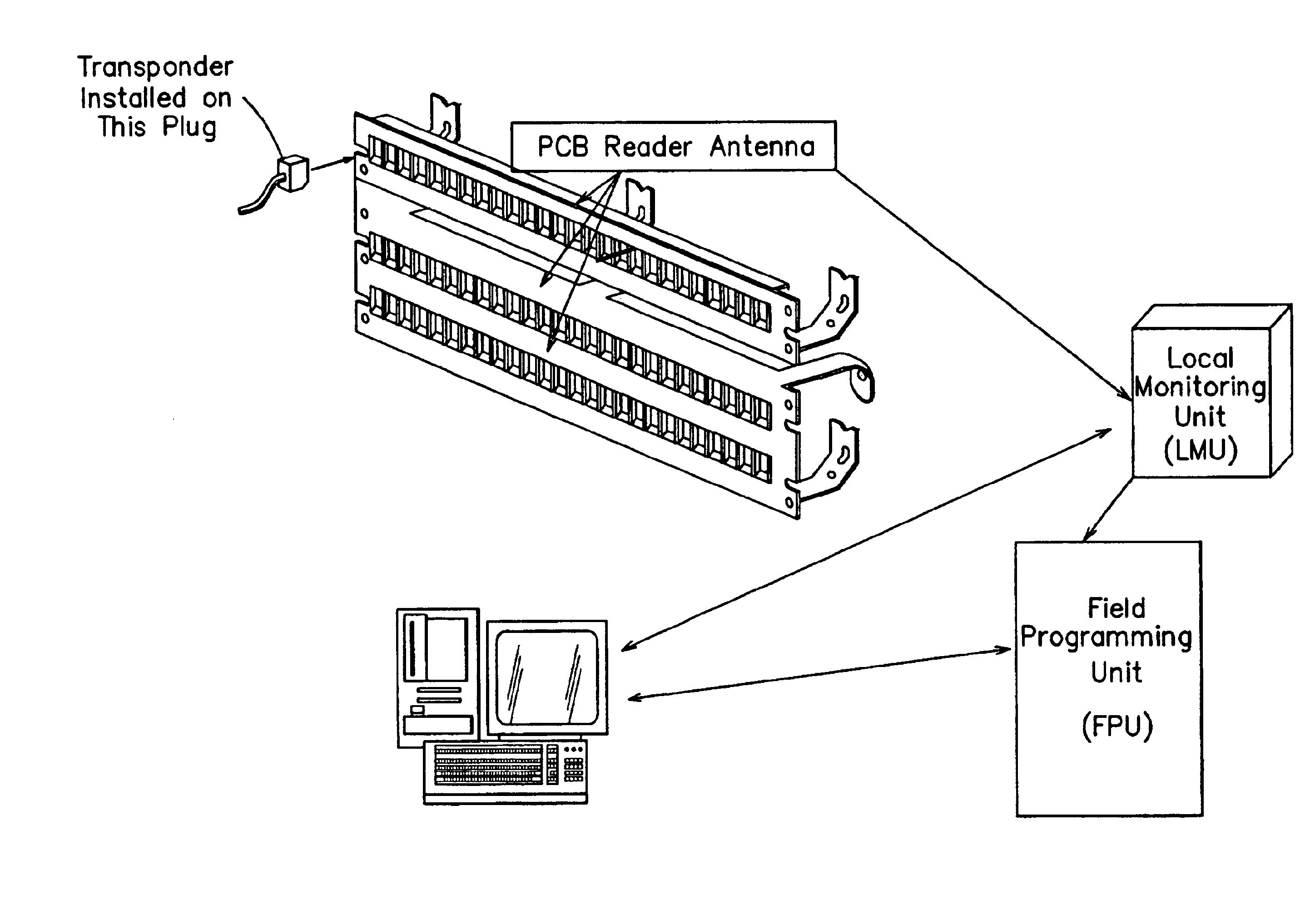
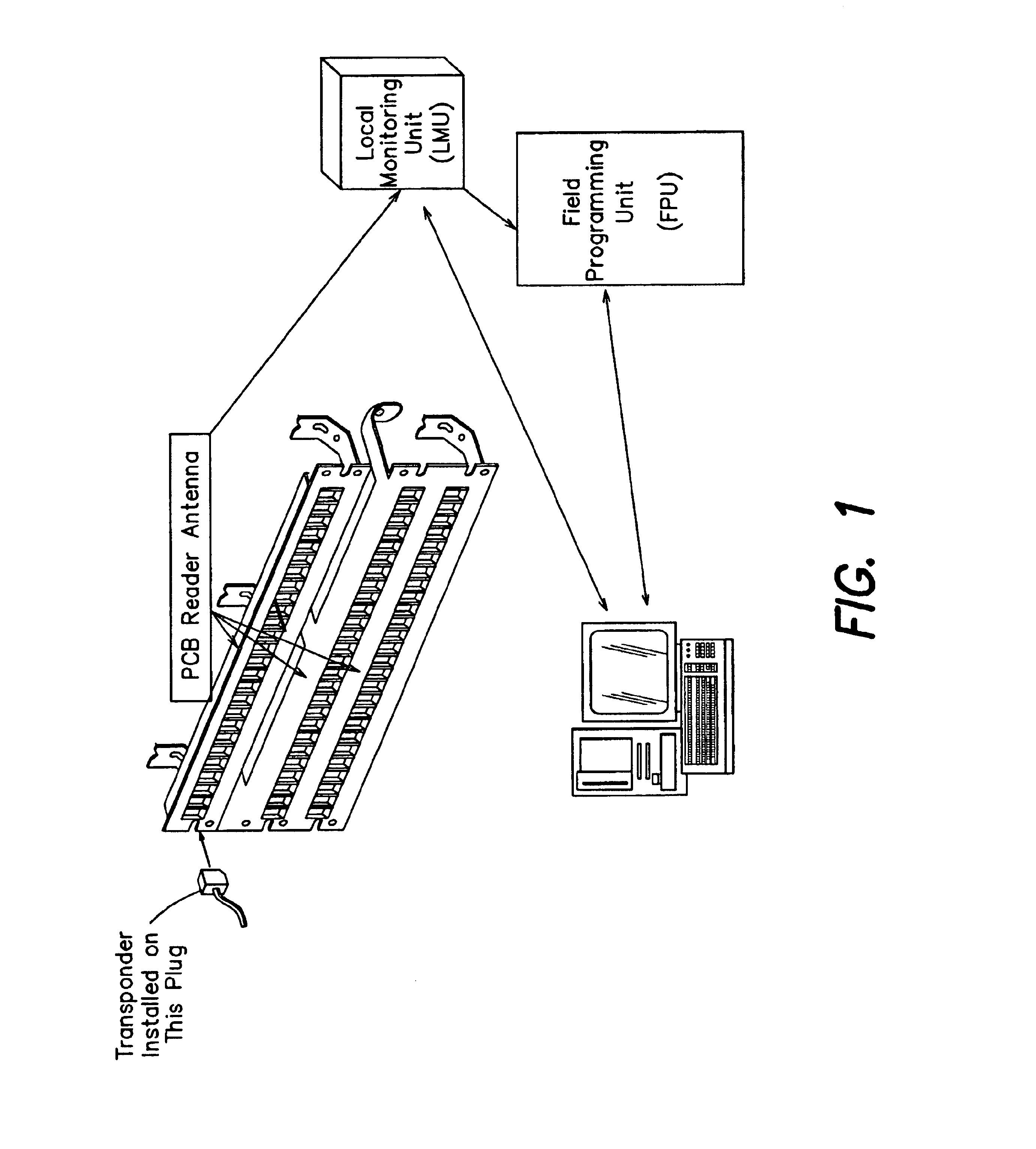
The invention is now illustrated by the following description of an embodiment and aspects thereof. The described embodiment provides a real time way to identify and manage connectivity in a structured cable system. The technology used is called "Radio Frequency Identification," or simply RFID. RFID is an automatic identification and information acquisition technology and consists of a sensing device, which transmits a radio-frequency signal to a specially designed tag, which responds with another radio message, thus identifying itself to the sensing device with a unique code.

Some advantages of the approach using RFID technology are:

Non-contact operation and wireless identification of both ends belonging to the same patch-cord;

Non-proprietary system that can be installed on existing, conventional cabling components;

Flexible, open architecture can be retrofitted to any existing or new copper and fiber structured cabling networks;

Eliminates clerical errors introduced when recording da...


PUM


Abstract

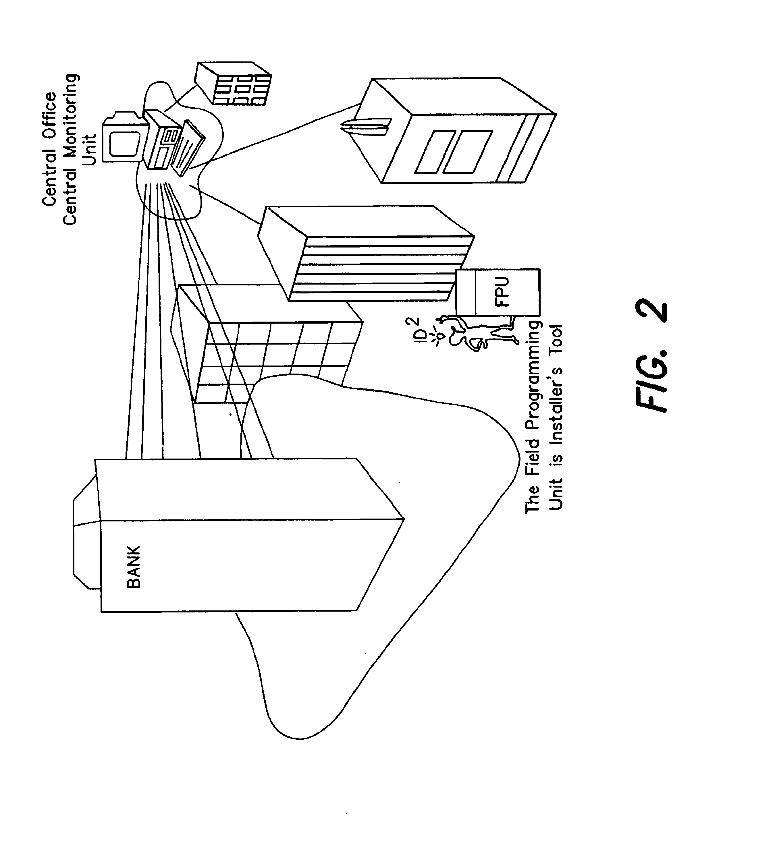
A system and method for monitoring connectivity in a cable system includes radio frequency identification (RFID) transponders on cable ends and RFID sensors at connection points. The RFID sensors are connected to a central monitoring system. Presence of a particular cable end at a particular connection point is detected and recorded by the central monitoring system.

Description

1. Field of the InventionThe present invention relates generally to methods and apparatus for monitoring the status of components of a cabling system.2. Related ArtIn modern construction, the telecommunications cabling system is part of many buildings' infrastructure. A building's cabling system should be flexible and adaptable to the needs of the people it serves. Thus, the cabling system is frequently a dynamic, changing entity. In order to facilitate this, some transition points have been added. These points are called "Telecommunications Closets" (TC) and their features and requirements are listed in the standard ANSI / TIA / EIA-569 (CSA T530), entitled "Commercial Building Standards for Telecommunications Pathways and Spaces" in effect on the filing date of this application. The TC is defined as the space that acts as the transition point between a network backbone, usually including one or more servers, routers, etc. and horizontal distribution pathways, going to the work area.In...

Claims


Application Information

Patent Timeline
Patent Type & Authority Patents(United States)
IPC IPC(8): G01R31/04G01R31/02H04Q1/02H04Q1/14
CPCG01R31/045G06K19/07758H04Q1/138H04Q1/144G01R31/69
Inventor STANESCU, MICHAEL D.
Owner NORDXCDT
Learn More