Dual eye motion detector assembly

a motion detector and assembly technology, applied in the field of motion detectors, can solve the problems of reducing sensor operation, reducing sensor operation, and unable to split the coverage area into smaller coverage areas for users

Inactive Publication Date: 2004-08-24
COLEMAN CABLE INC
View PDF13 Cites 64 Cited by
  • Summary
  • Abstract
  • Description
  • Claims
  • Application Information

AI Technical Summary

Benefits of technology

to provide such a motion detector assembly that is less likely to fail over time due to dirty or fogged conditions.
When a wide, combined viewing area is desired, the main and secondary motion sensor heads are pivotally adjusted on the mounting box so that their separate viewing zones slightly overlap thereby providing a total coverage zone of approximately 330 degrees. The main and secondary motion sensor heads may be independently twisted towards their desired viewing areas and independently elevated to obtain different viewing areas depths. Also, both the main and secondary motion sensor heads use single lens infrared sensors rather than multiple lens or mirror sensors thereby making them less susceptible to dirt or fog.

Problems solved by technology

One problem with such controls is that the viewing angle of the sensor box is limited to approximately fifty (50) feet on both sides of the normal axis of the lens of the sensor box (110 degrees total).
Unfortunately, the lenses and reflective faces used on such detectors may become dirty or fogged over time, which reduces sensor operation
Another drawback with using wide-angle single detectors is that the user is unable to split the coverage area into smaller coverage areas.
Another drawback with single wide angle motion detectors is that their viewing fields have uniform height or depth.
The heights or depths of sections in their viewing fields can not be selectively adjusted.

Method used


Image

  • Dual eye motion detector assembly
  • Dual eye motion detector assembly
  • Dual eye motion detector assembly

Examples


Embodiment Construction

)

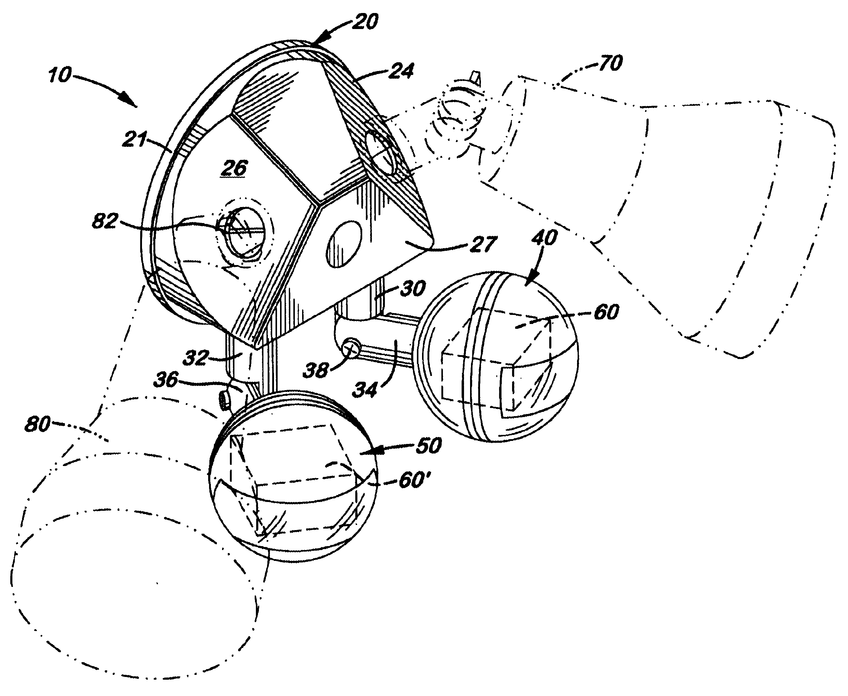
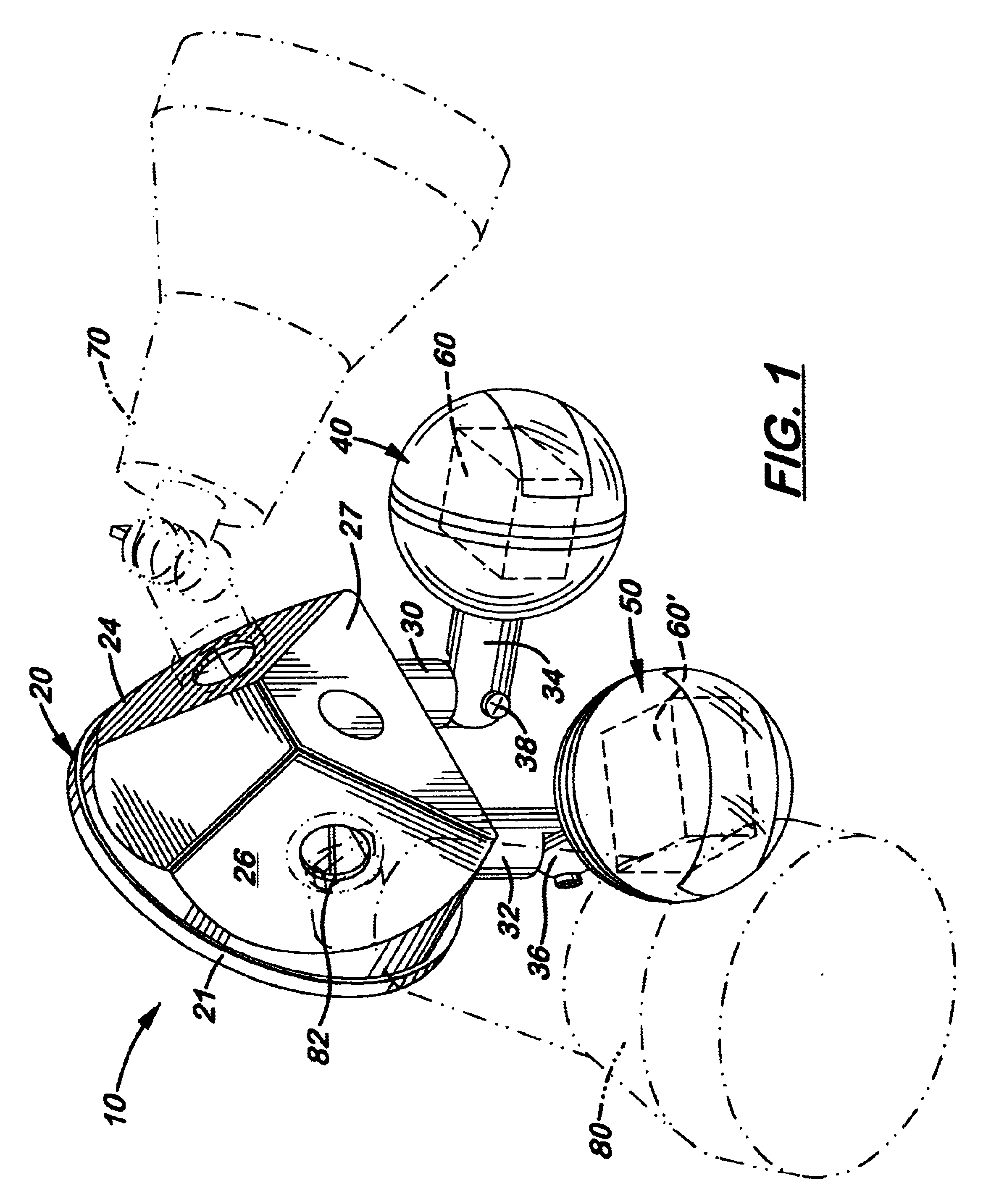
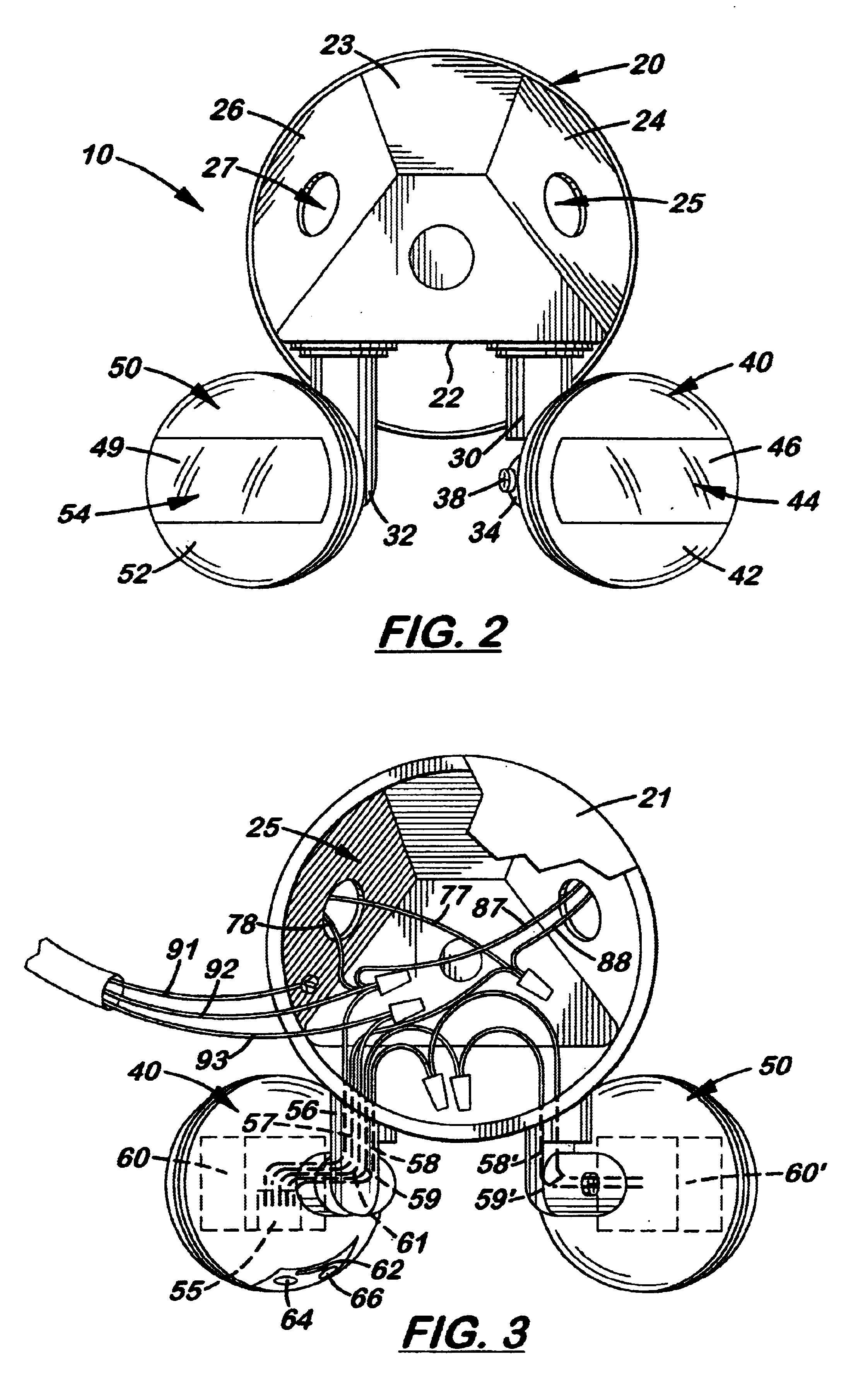
Referring to the accompanying FIGS. 1-9, there is shown and described a dual motion detector assembly 10 comprising a main motion sensor head 40 and a secondary motion sensor head 50 both mounted on a mounting box 20. Located inside the main motion sensor head 40 and the secondary motion sensor head 50 are standard, single lens motion sensors 60, 60' respectively, each designed to provide an approximate 110-degree viewing zone as shown in FIG. 8. Both the main motion sensor head 40 and secondary motion sensor head 50 are pivotally mounted to rigid arms 34, 36, respectively, that are connected to vertically aligned, rotatably adjusted posts 30, 32, respectively, that extend downward from the bottom surface 21 mounting box 20.

In the preferred embodiment, the mounting box 20 is a five-sided structure with a flat mounting plate 21 selectively attached over its rear opening 25. The bottom surface 22 of the mounting box 20 is flat and horizontally aligned and opposite a flat, diagonally ...


PUM


Abstract

A dual eye motion detector assembly comprising a main infrared sensor head and a secondary infrared sensor head mounted on a mounting box. The main motion sensor head is pivotally mounted to the mounting box and contains a standard infrared motion sensor with an approximate 90 to 180 degree viewing zone. The secondary motion sensor head is also pivotally and independently mounted to the mounting box and contains its own standard infrared motion sensor with an approximately 90 to 180 degree viewing zone. The two motion sensors in the main and secondary motion sensors heads are connected to a circuit panel located the main sensor head. Control switches are mounted on the sides of the main infrared sensor head to control sensitivity and timing. Outside electrical current is delivered to the circuit panel and divided into local circuits to control the operation of at least one lamp so that when an infrared-emitting object passes into the viewing zone of either sensor head, the lamp is automatically activated.

Description

1. Field of the InventionThis invention pertains to motion detectors and, more particularly to motion detectors with adjustable wide viewing areas.2. Description of the Related ArtMotion detector lighting controls that include an infrared sensor box and a pair of lamp holders, all rotatably mounted to a mounting box, have been known for years. When an infrared emitting object, such as an animal, enters the viewing zone of the infrared sensor located inside the infrared sensor box, the lamps connected to the infrared sensor are automatically activated to illuminate the desired area at which the lamps are aimed. When the object leaves the viewing zone, the lamps automatically turn off after a pre-determined amount of time.One problem with such controls is that the viewing angle of the sensor box is limited to approximately fifty (50) feet on both sides of the normal axis of the lens of the sensor box (110 degrees total). When the infrared emitting object approaches the light fixture f...

Claims


Application Information

Patent Timeline
Patent Type & Authority Patents(United States)
IPC IPC(8): G08B13/193G08B13/189H05B37/02
CPCF21V17/02F21V23/0442G08B13/193H05B37/0227Y02B20/44F21S8/033H05B47/13Y02B20/40
Inventor LEEN, MONTE A.
Owner COLEMAN CABLE INC
Why Eureka
Try Eureka