Low harmonic rectifier circuit

a low-harmonic rectifier and circuit technology, applied in the direction of electric variable regulation, process and machine control, instruments, etc., can solve the problems of increased cost, unsatisfactory harmonic current, and large size of harmonic curren

Inactive Publication Date: 2004-08-10
ABB IND +2
View PDF1 Cites 33 Cited by
  • Summary
  • Abstract
  • Description
  • Claims
  • Application Information

AI Technical Summary

Problems solved by technology

These harmonic currents are not desirable because of their adverse effects (such as energy losses and malfunction of the sensitive equipment) on the utility network.
But the larger the value of the inductor, the bigger it is in size and the more expensive it is.

Method used


Image

  • Low harmonic rectifier circuit
  • Low harmonic rectifier circuit
  • Low harmonic rectifier circuit

Examples


Embodiment Construction

)

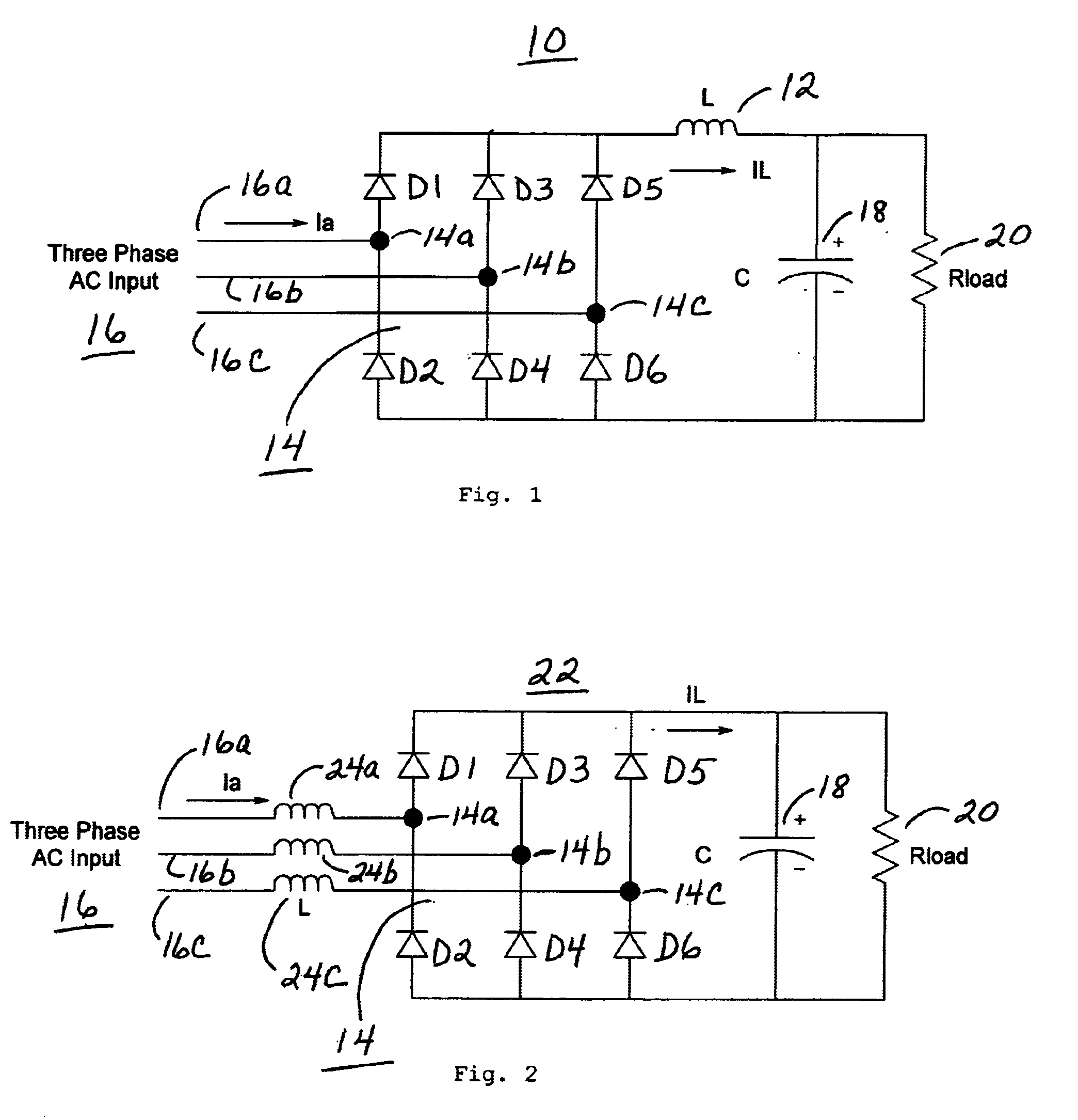
Referring now to FIG. 1, there is shown a three phase rectifier system 10 that has a dc side filter inductor 12 labeled as L. As is shown in FIG. 1, the system has bridge 14 connected directly to the three phases 16a, 16b and 16c of the ac input 16. Bridge 14 has six diodes D1 to D6. Input phase 16a is connected to diodes D1 and D2 at junction 14a, input phase 16b is connected to diodes D3 and D4 at junction 14b, and input phase 16c is connected to diodes D5 and D6 at junction 14c. Filter inductor 12 is connected between the cathode of each of diodes D1, D3 and D5 and one terminal of a capacitor 18, labeled as C, which is in parallel with load 20 represented in FIG. 1 by a resistor labeled Rload. The other terminal of capacitor 18 is connected to the anode of each of diodes D2, D4 and D6.

FIG. 2 shows a three phase rectifier system 22 in which bridge 14 is connected to the three phases of ac input 16 through three filter inductors 24a, 24b and 24c. Except for the difference in the l...


PUM

PropertyMeasurementUnit
inductanceaaaaaaaaaa
dc voltageaaaaaaaaaa
frequencyaaaaaaaaaa

Abstract

Non-linear inductor(s) are used to reduce the percent total harmonic distortion of the harmonics in the line currents in the input side rectifier system of an ac drive system. Several constructions for the non-linear inductor(s) are described. The non-linear inductor(s) may be constructed from E and I laminations. The gap depends on the construction of the middle leg of the E laminations and may have a step with a constant spacing or a variable spacing which depends on the stacking of the laminations. Alternatively the non-linear inductor(s) may be constructed from a toriodal core that either has a step gap or a variable type gap.

Description

This invention relates to the input side rectifier in an ac drive system and more particularly to the inductors used therein.DESCRIPTION OF THE PRIOR ARTThe two main subsystems of a modern ac drive system are the input side rectifier system and output inverter system. The purpose of the rectifier system is to convert input ac voltage, from the utility source, into an intermediate dc voltage and the purpose of the inverter system is to convert the intermediate dc voltage into a variable frequency and a variable magnitude ac output voltage. The rectifier systems are also used in equipment such as welding, electroplating and uninterruptible power supplies.The input rectifier system consists of a three-phase diode bridge, either ac or dc side inductor(s) and dc bus capacitors. The three-phase diode bridge converts input ac voltage into dc voltage. The inductor(s) and capacitor(s) serve as a smoothing filter for the intermediate dc voltage. Such a rectifier system, when connected to a si...

Claims


Application Information

Patent Timeline
Patent Type & Authority Patents(United States)
IPC IPC(8): H01F3/14H01F38/00H01F3/00H01F38/02H02M1/12
CPCH01F3/14H01F38/023H02M1/126Y10T29/49075Y10T29/49078Y10T29/4902Y10T29/49069
Inventor GOKHALE, KALYAN P.VALLINMAKI, ALPO K.SODO, NICKLAS JAN ANDERS
Owner ABB IND
Why Eureka
Try Eureka