Creeping wave technique for mill roll inspection

a technology of mill roll and surface wave, which is applied in the direction of manufacturing tools, instruments, specific gravity measurement, etc., can solve the problems of inability to develop a commercial success of automation of surface wave technique for roll inspection, the sensitivity of this wave mode to the presence of fluid, and the rapid propagation of surface cracks to failur

Inactive Publication Date: 2004-08-03
INNERSPEC TECH
View PDF4 Cites 5 Cited by
  • Summary
  • Abstract
  • Description
  • Claims
  • Application Information

AI Technical Summary

Benefits of technology

It is another object of this invention to provide an ultrasonic inspection that does not require the drying of the roll surface in front of the transducer assembly prior to performing an inspection.
It is another object of this invention to provide a real-time ultrasonic inspection that can be performed during the grinding operation of a mill roll without the need to remove grinding cooling fluid.
It is still another object of this invention to provide an ultrasonic inspection of mill rolls that is sensitive to surface and near surface defects such as cracks and porosity, without being effected by surface contaminates such as oil or water.

Problems solved by technology

The result is the formation of surface cracks that can quickly propagate to failure if not detected and removed.
However, automation of the Surface Wave technique for roll inspection never developed into a commercial success due to problems associated with water on the roll surface as described below.
A serious complication to using Surface Waves for roll inspection is the sensitivity that this wave mode has to the presence of fluid, such as water drops, on the roll surface.
This is made more difficult since cooling fluids are used during the grinding of the roll surface.
During an automated scan where the roll is being rotated, this couplant layer will leave a trail of water that will interfere with the data taken on the subsequent rotation.
This type apparatus has been found to be unreliable in practice since it cannot eliminate all surface water especially during grinding when water is splashed around the roll.
The use of Surface Waves has been found to be impractical while grinding since the roll has to be completely dry in front of the ultrasonic transducer to avoid the possibility of a water drop reflection being interpreted as a surface crack.
However, this type of ultrasonic transducer does require that the mill roll be completely dried prior to inspection, thus making it impractical for use during the grinding process.

Method used


Image

  • Creeping wave technique for mill roll inspection
  • Creeping wave technique for mill roll inspection
  • Creeping wave technique for mill roll inspection

Examples


Embodiment Construction

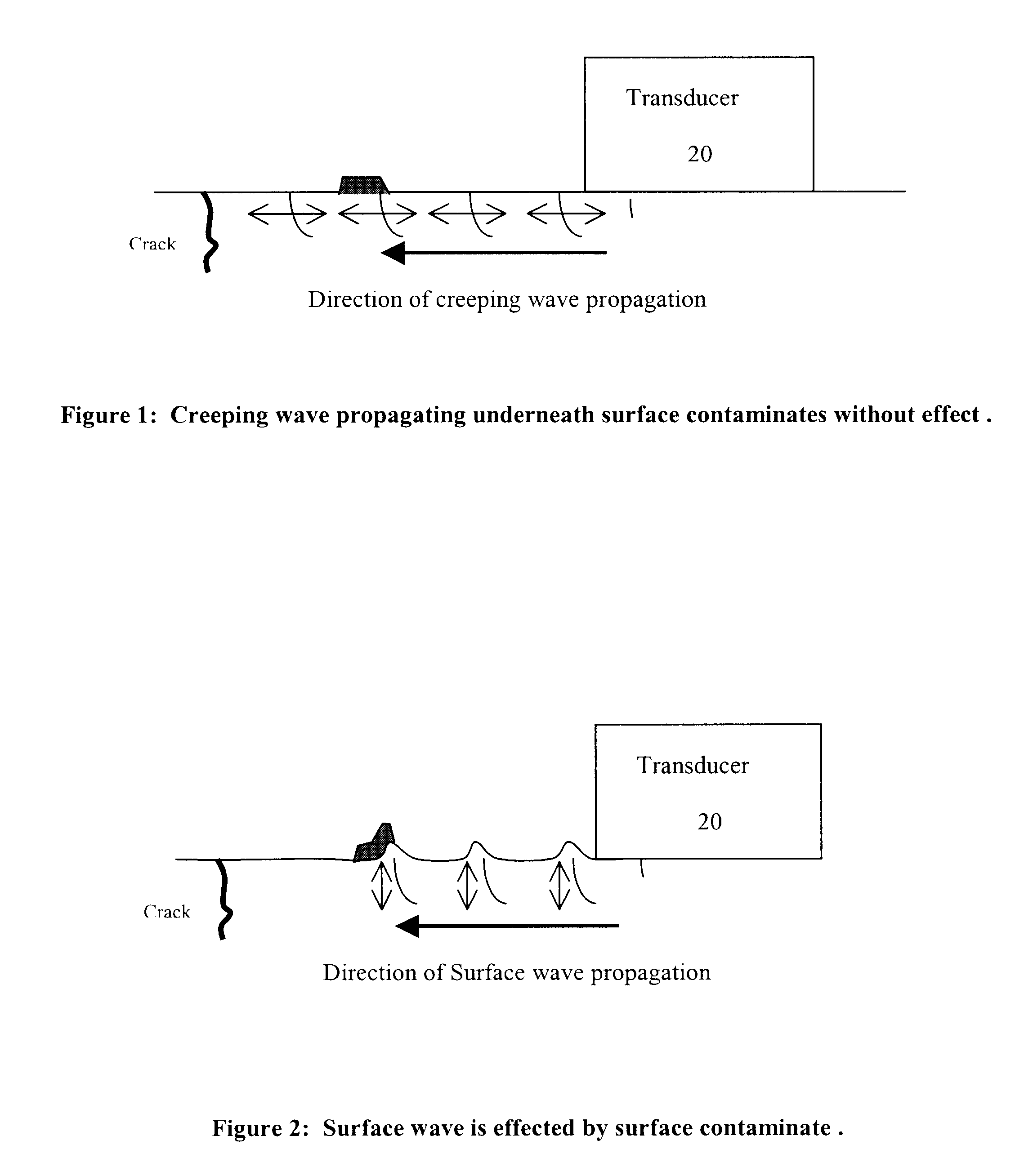
The present invention is an ultrasonic inspection system for the detection of surface breaking and near surface defects on mill rolls that uses Creeping Waves, making it possible to inspect a wet roll.

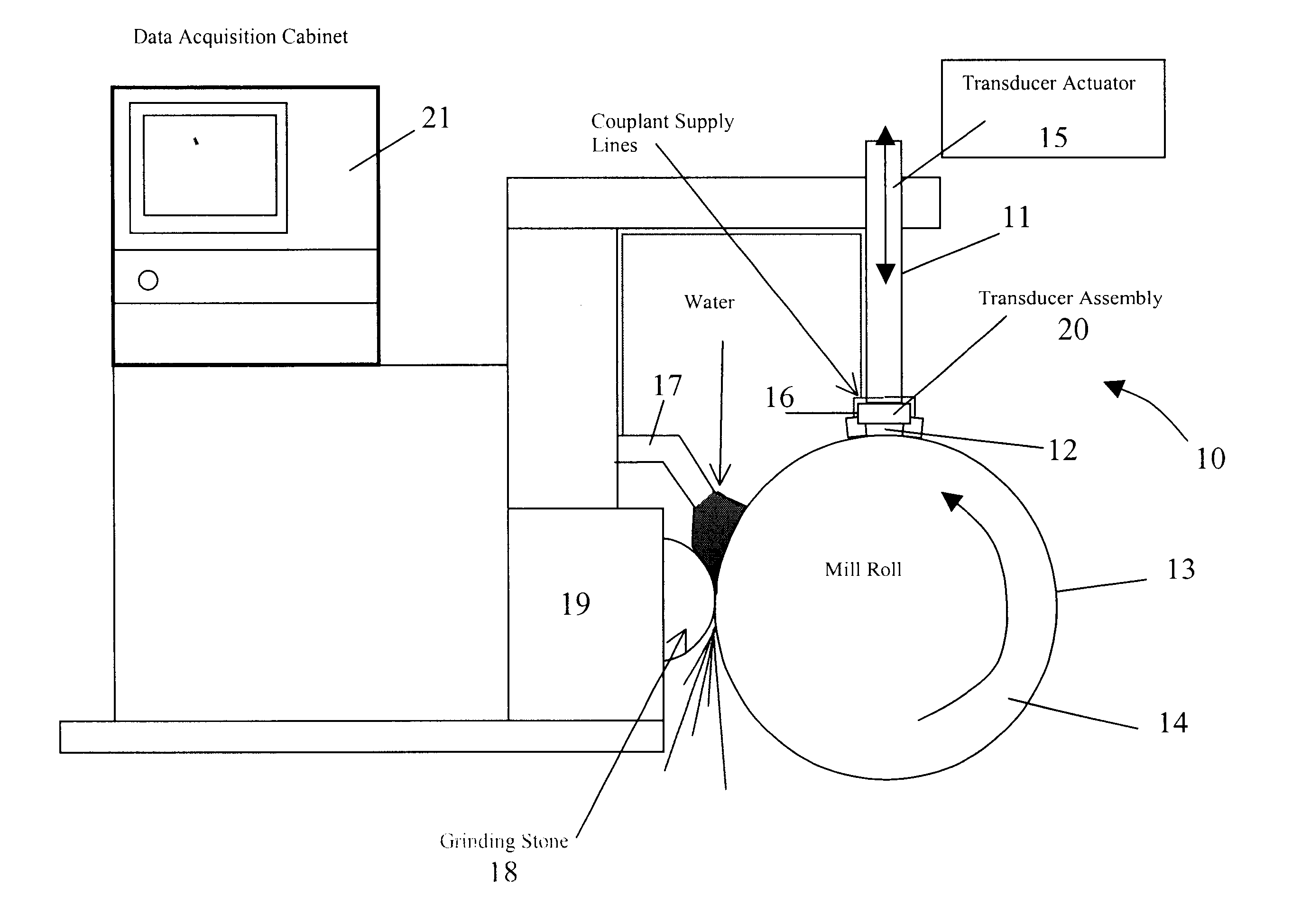
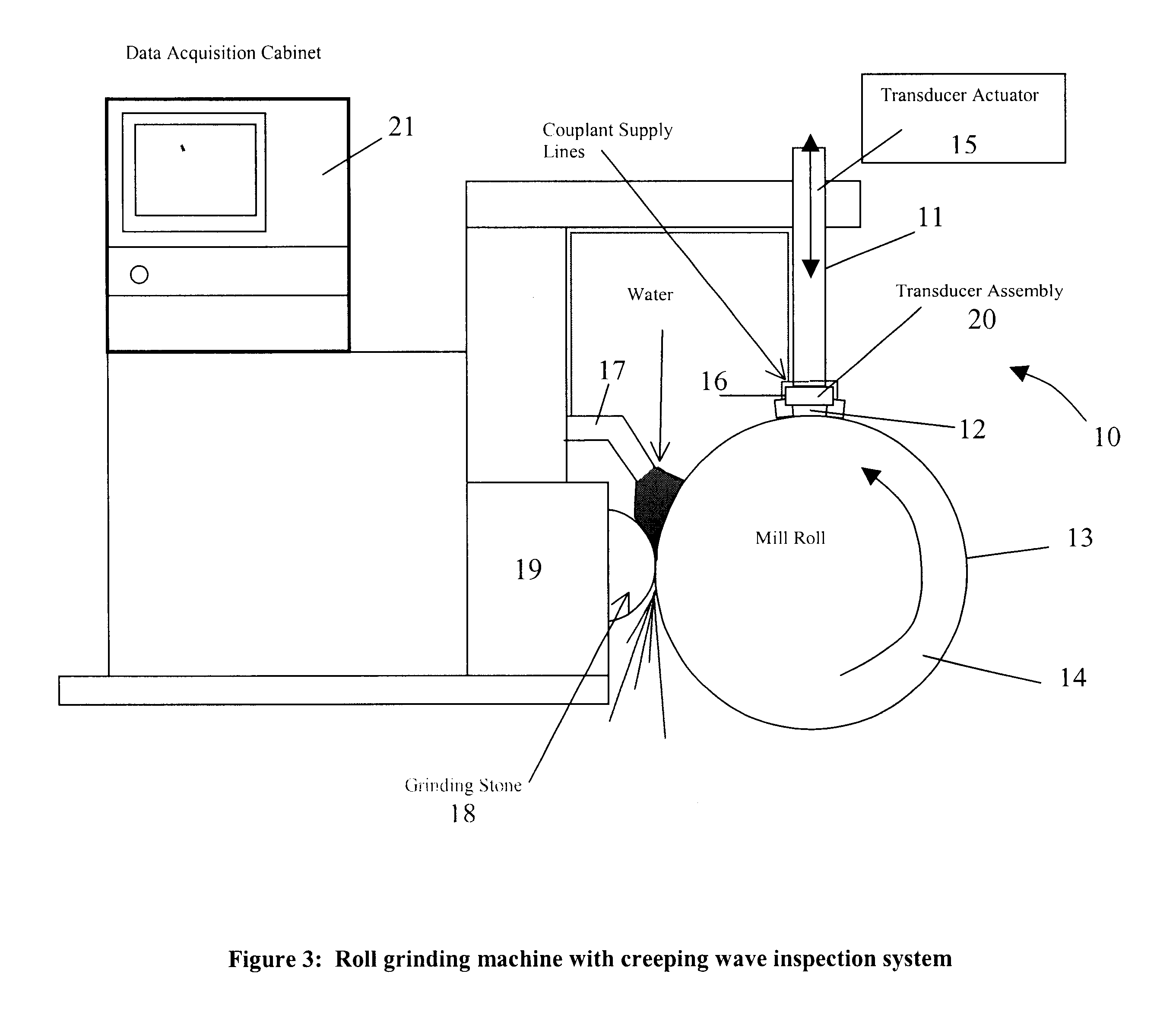
FIG. 3 is an illustration of the mill roll inspection system mounted on a mill roll grinder 19 with stone 18. The inspection system is comprised on four basic components: the transducer assembly 20, the transducer actuator 15, the couplant delivery system 17, and the data acquisition system 21.

The transducer assembly 10 consists of one of more transducers 20 mounted in an articulated holder that allows the bottom surface 12 of each transducer to ride against the surface 13 of the roll 14 over a range of roll diameters. Each transducer can be mounted in any orientation on the mill roll, depending on the orientation of the defect to be detected. Multiple transducers can be used to detect defects of various orientations.

Each transducer 20 is designed to generate a creeping wave, which is ...


PUM

PropertyMeasurementUnit
incident angleaaaaaaaaaa
angleaaaaaaaaaa

Abstract

A method and apparatus for simultaneously inspecting and grinding roll mills which utilizes a transducer assembly which produces a creeping wave propagation in conjunction with a couplant fluid provider and data acquisition circuit which allows the operator to see the crack and imperfections in on the surface of the mill rolls as they are rotated and to grind them off.

Description

1.0 FIELD OF INVENTIONThis invention relates, overall to an automated ultrasonic inspection system of mill rolls used in the process of metal fabrication, and, in particular to the use of creeping waves as the specific wave mode used for the detection of surface and near surface defects such as cracks, porosity, etc.2.0 BACKGROUNDMill rolls are an integral component of many metal fabricating processes. The rolling surface of a mill roll is typically subjected to high cyclic stresses created by direct loading and / or thermal cycles. The result is the formation of surface cracks that can quickly propagate to failure if not detected and removed. For this reason, mill rolls are periodically removed from service and placed in a roll grinding machine that mechanically removes a work hardened layer of material from the rolling surface. The rolls are then inspected to assure that all cracks are removed prior to reintroducing back into the mill.The most common ultrasonic method for roll inspe...

Claims


Application Information

Patent Timeline
Patent Type & Authority Patents(United States)
IPC IPC(8): B24B5/00B24B5/16B24B49/10B21B28/02B21B28/00B24B5/37G01N29/04G01N29/28
CPCB24B5/167B24B49/10G01N29/043G01N29/28B21B28/02G01N2291/0421G01N2291/0422G01N2291/044G01N2291/2626Y10S451/91
Inventor BUTTRAM, JONATHAN D.
Owner INNERSPEC TECH
Why Eureka
Try Eureka