
Method for operating a burner and burner with stepped premix gas injection

a burner and premix technology, applied in the direction of lighting and heating apparatus, combustion types, combustion using lump and pulverulent fuel, etc., can solve the problems of increasing no.sub.x emissions, only being able to operate optimally, and increasing the operating range of known burners, so as to improve the flame stability and reduce emissions

Inactive Publication Date: 2004-08-03
ANSALDO ENERGIA SWITZERLAND AG
View PDF14 Cites 34 Cited by
  • Summary
  • Abstract
  • Description
  • Claims
  • Application Information

AI Technical Summary

Benefits of technology

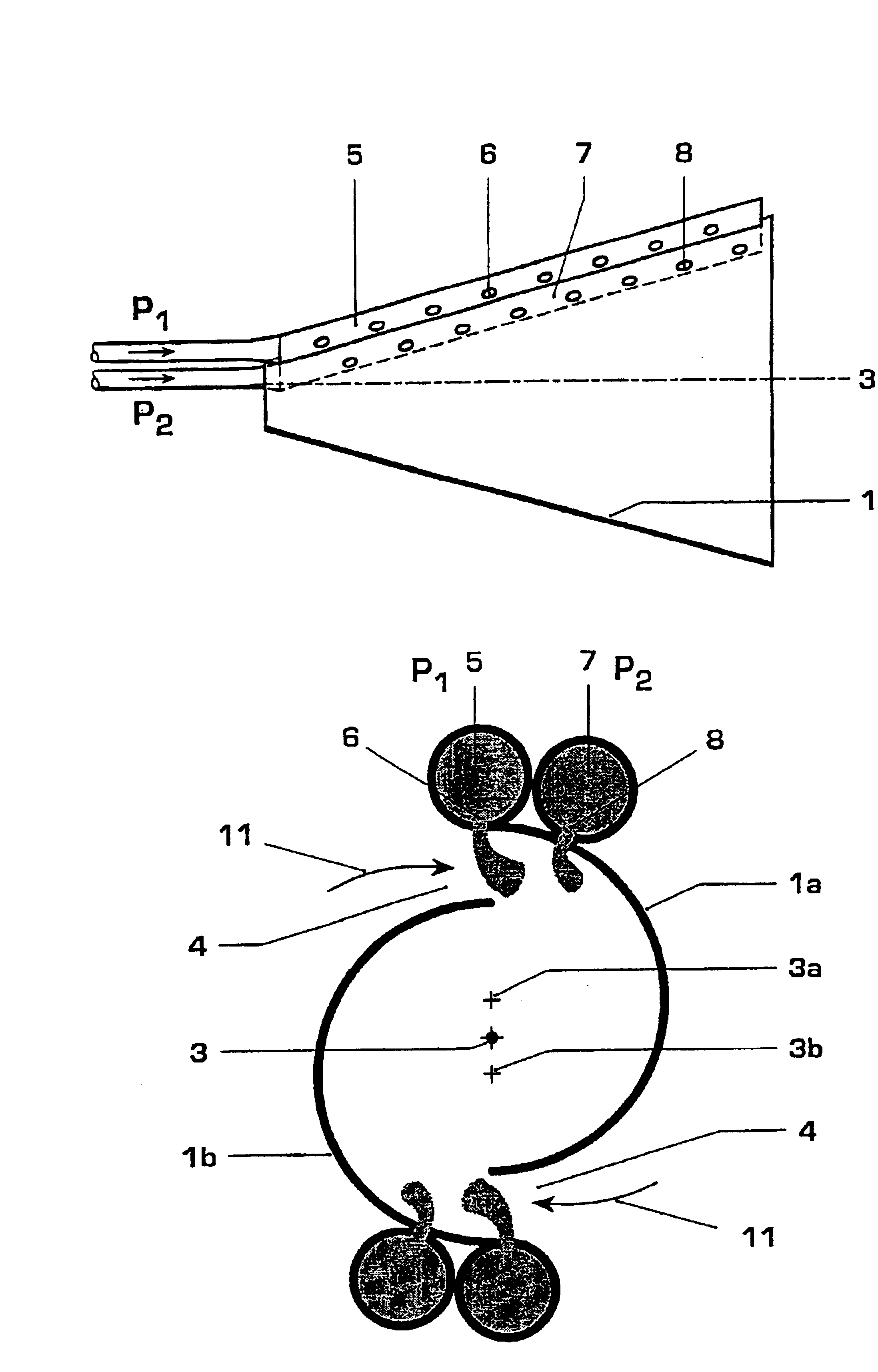
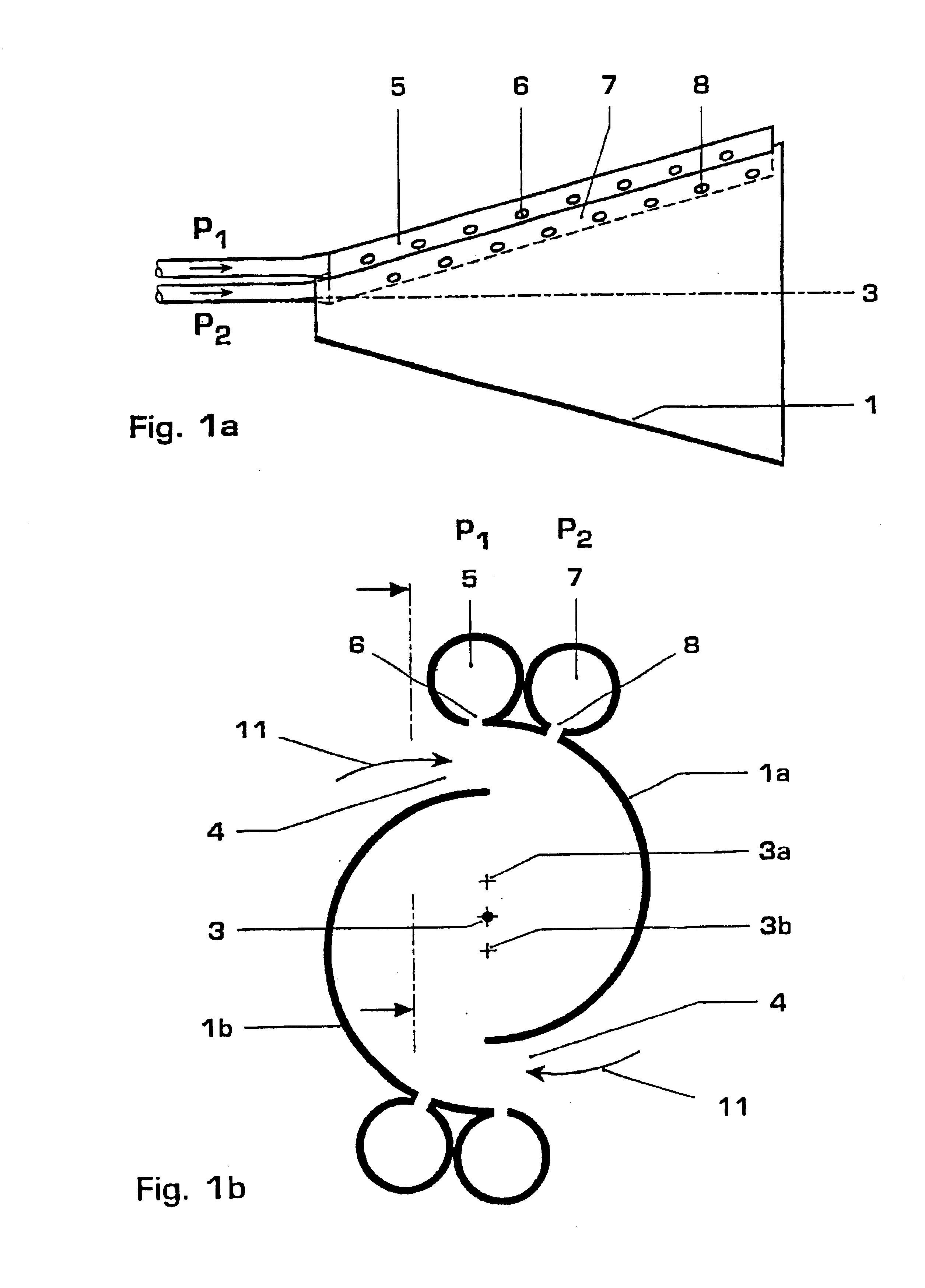
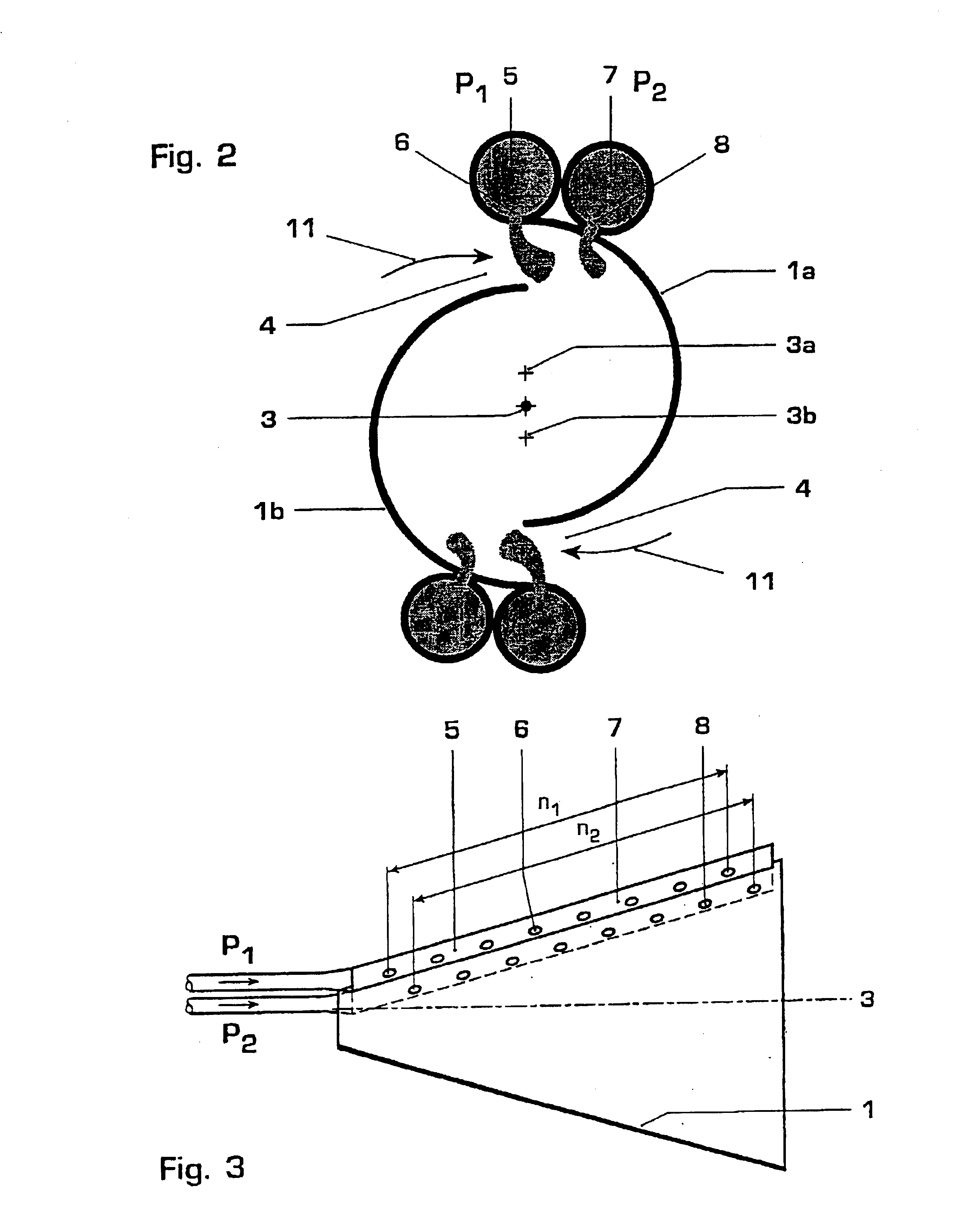
The present invention relates to a method of operating a burner with improved mixing of fuel and air, which reduces NOx emissions and improves stability and flame-out limits. The method involves introducing fuel into a swirl space through a conical swirl generator with a cross-sectional step, which generates a stable swirl flow. The fuel is injected through outlet openings in the swirl generator, which are distributed in the direction of the burner longitudinal axis. The method also allows for independent control of fuel injection in different parts of the burner, such as the front or the rear, to optimize mixing and stability for different load, gas quality, and preheat temperatures. The invention also provides a premix burner design with improved mixing and fuel distribution for low NOx values during combustion.

Problems solved by technology

The supply of the pilot gas in the outlet region of the burner leads, however, to increased NO.sub.x emissions because it is only inadequate mixing with the combustion air which can take place in this region.
The known burners can therefore only be operated optimally for quite specific value ranges of these parameters.
A problematic feature in the operation of premix burners, particularly in gas turbines, is the part-load range because, in this range, the combustion air is mixed with only comparatively small fuel quantities.
In the case of the complete mixing of the fuel with the whole of the air, however, a mixture occurs which is no longer capable of being ignited, particularly in the lower part-load range, or is only capable of forming a very unstable flame.
This can lead to damaging combustion pulsations or to the flame becoming completely extinguished.
This, however, is only possible in the case of multi-row burner arrangements.
In the case of single-row annular combustion chambers, this technology has the disadvantage that a temperature profile, which is non-uniform in the peripheral direction, appears at the combustion chamber outlet.
This results, on the one hand, in superior flame stability but, on the other, in high emission values and further technical disadvantages in operation.
In this case, the geometry of the swirl generator is unimportant.

Method used


Image

  • Method for operating a burner and burner with stepped premix gas injection
  • Method for operating a burner and burner with stepped premix gas injection
  • Method for operating a burner and burner with stepped premix gas injection

Examples


Embodiment Construction

The following figures show the burners in strongly diagrammatic embodiment, so that only the features essential for the respective explanation are emphasized in each case. The specialist is familiar with the further arrangement of the burners represented, inter alia from the documents cited as the prior art, which represent an integrated constituent of the present description. In addition, reference is made in some cases to the injection of gaseous fuel in the exemplary embodiments. It is, however, obvious per se that liquid fuels can also be introduced into the combustion air flow via the fuel outlet openings. The fuel is, in addition, referred to as premix fuel; it is obvious per se that a part of the total fuel quantity can also be introduced in certain load ranges as pilot fuel in order to further increase the flame stability. No supply conduits for pilot fuel are shown in any of the figures because they are not essential to the invention; given knowledge of the prior art, the s...


PUM


Abstract

The present invention relates to a method of operating a burner, which comprises at least one first fuel supply conduit (5) with a first group of fuel outlet openings (6), essentially arranged in the direction of a burner longitudinal axis (3), for a first premix fuel quantity and one or a plurality of second fuel supply conduits (7) with a second group of fuel outlet openings (8), essentially arranged in the direction of the burner longitudinal axis (3), for a second premix fuel quantity, it being possible to admit fuel to the second fuel supply conduits (7) independently of the first fuel supply conduit (5). In the method, both fuel supply conduits (5, 7) are operated with the same fuel. By means of the present method of operating a burner, optimum mixing conditions can be set even in the case of different loads, gas qualities or gas preheat temperatures.

Description

The present invention relates to a method of operating a burner, which has at least one first fuel supply conduit with a first group of fuel outlet openings, essentially arranged in the direction of a burner longitudinal axis, for the introduction of a first premix fuel quantity into a swirl space and one or a plurality of second fuel supply conduits with a second group of fuel outlet openings essentially arranged in the direction of the burner longitudinal axis, it being possible to admit fuel to the second fuel supply conduits independently of the first fuel supply conduit. The invention also relates to a burner which can be advantageously operated by means of the method. The combustion spaces of gas turbines are a preferred field of employment for such burners; in addition such burners are, for example, also employed in atmospheric boiler firing systems.RELATED ARTA conical burner consisting of a plurality of shells, a so-called double-cone burner, is known from EP 0 321 809. A s...

Claims


Application Information

Patent Timeline
Patent Type & Authority Patents(United States)
IPC IPC(8): F23D17/00F23R3/28F23C7/00F02C9/26F23C99/00F23D14/02F23D14/24F23R3/12F23R3/32F23R3/34
CPCF23C7/002F23D17/002F23R3/286F23C2900/07002F23D2900/14021
Inventor EROGLU, ADNANHELLAT, JAANSTUBER, PETER
Owner ANSALDO ENERGIA SWITZERLAND AG
Learn More