
Continuous hydrogenation process

a hydrogenation process and continuous technology, applied in chemical/physical/physical-chemical processes, hydrogen peroxide, organic chemistry, etc., can solve the problems of large pressure drop, unattractive route, and slow transfer of gaseous hydrogen into the solution and onto the catalyst surfa

Inactive Publication Date: 2004-06-29
EVONIK OPERATIONS GMBH
View PDF14 Cites 5 Cited by
  • Summary
  • Abstract
  • Description
  • Claims
  • Application Information

AI Technical Summary

Benefits of technology

As a result, the pressure drop in the hydrogenation reactor is reduced quite substantially, which leads to a reduction in the energy costs. Alternatively, the total circulating quantity can be increased at a constant speed of the circulating pump, which leads to a higher velocity and space-time yield and thus, ultimately, to an increase in capacity.
In addition to the bubble size, the stability of the bubbles is also significant. The bubbles should be prevented from coalescing, which would result in inadequate distribution of the hydrogen in the liquid phase.

Problems solved by technology

A great disadvantage of this type of reactor is the slow transfer of the gaseous hydrogen into the solution and on to the catalyst surface.
Considerable investment costs and the fact that only a fraction of the hydrogen required in the reaction can be brought into solution make this route unattractive.
It is disadvantageous in this process described in EP-A-111 133 that the mixing devices for the substance to be hydrogenated and the hydrogen lead to large pressure drops, particularly when tubular reactors are to be operated at the high circulating flows and circulation rates specified, and therefore a higher input of energy is necessary.
However, it has now been shown that, even when the gas and liquid phase are premixed upstream of the hydrogenation reactor, the conversion is not reduced.
The bubbles should be prevented from coalescing, which would result in inadequate distribution of the hydrogen in the liquid phase.

Method used


Image

  • Continuous hydrogenation process
  • Continuous hydrogenation process

Examples


Embodiment Construction

The process according to the invention is particularly suitable in the above-mentioned process for the catalytic hydrogenation of

substituted anthraquinones or mixtures of substituted anthraquinones,

the partially ring-hydrogenated alpha- and beta-tetrahydro derivatives thereof and mixtures of a) and b)

to the corresponding anthrahydroquinones and tetrahydro-anthrahydroquinones.

In particular, 2-alkyl-substituted anthraquinones, the alkyl residue of which can contain 1 to 8 C atoms and can be linear or branched, are used. Examples of these are 2-ethyl, 2-amyl und 2-tert.-butyl anthraquinone and their tetrahydro derivatives.

Other compounds that can be advantageously hydrogenated by the process according to the invention are olefins, aromatic and heteroaromatic rings, carbonyl compounds and nitriles.

The substance to be hydrogenated can be introduced as such or in solution. Anthraquinones are preferably dissolved in a mixture of solvents containing a quinone solvent and a hydroquinone solv...


PUM

PropertyMeasurementUnit
diameteraaaaaaaaaa
diameteraaaaaaaaaa
specific interfacial surface tensionsaaaaaaaaaa

Abstract

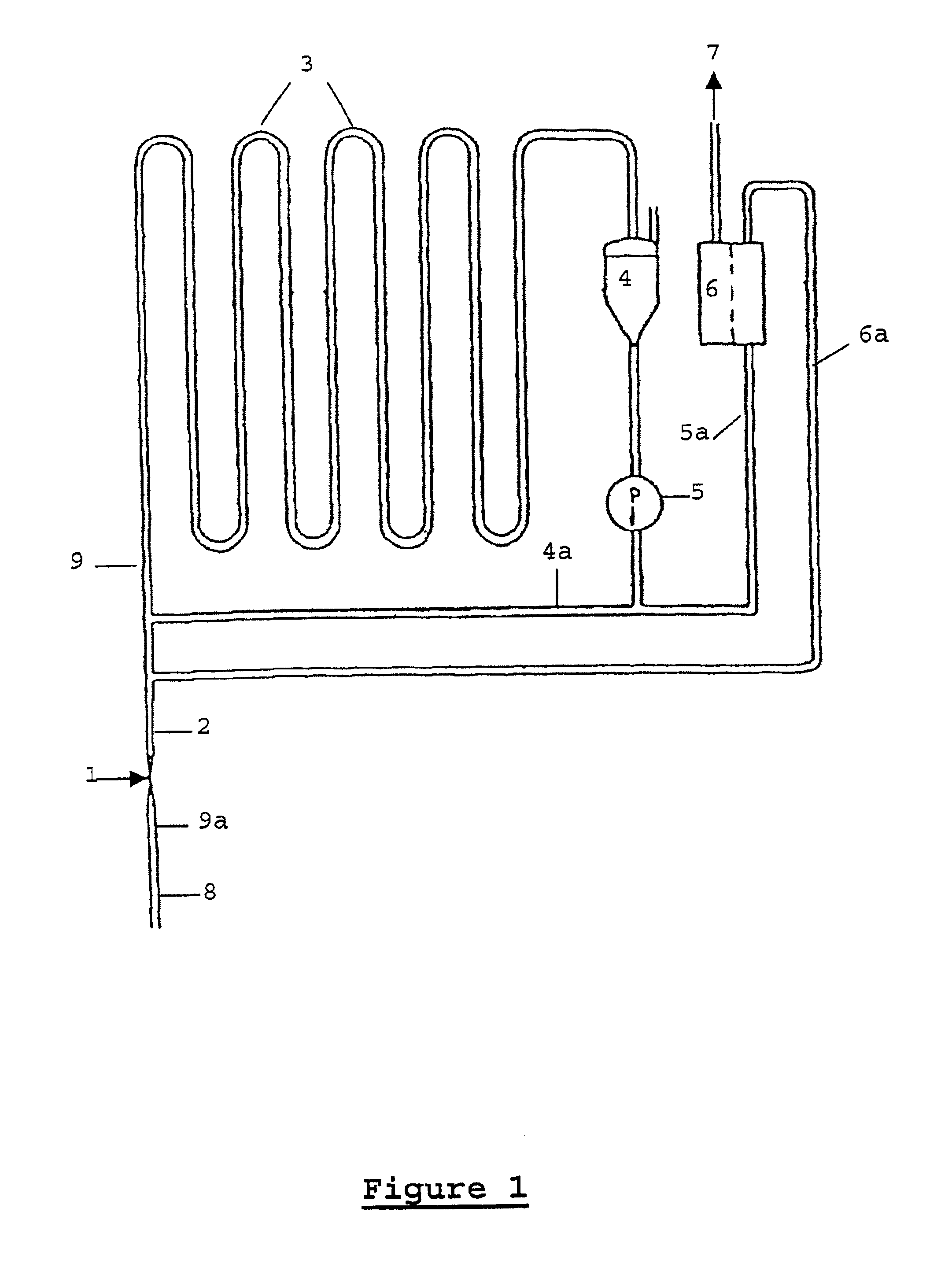
A continuous catalytic hydrogenation process, in which a reaction mixture containing the substance to be hydrogenated, the hydrogenation product, hydrogen and the hydrogenation catalyst suspended in the reaction mixture is recirculated in a reactor. Part of the hydrogenation product is removed from the reactor and the substance to be hydrogenated and hydrogen are fed into the reaction. In this process the substance to be hydrogenated and the hydrogen are mixed before entering the reactor. A venturi nozzle is particularly suitable as the mixing device.

Description

INTRODUCTION AND BACKGROUNDThe present invention relates to a continuous catalytic hydrogenation process, in which the hydrogenation catalyst suspended in the reaction mixture is recirculated. This process is particularly suitable for the hydrogenation step in the anthraquinone process for the production of hydrogen peroxide.In known hydrogenation processes the catalyst is generally used as a fixed bed, as a supported or as a suspended catalyst.In the fixed bed reactor the catalyst is applied to a support. A great disadvantage of this type of reactor is the slow transfer of the gaseous hydrogen into the solution and on to the catalyst surface.Various ways of bringing the hydrogen into solution more rapidly have been suggested. U.S. Pat. No. 2,837,411 describes the saturation of the solution with hydrogen before hydrogenation in a separate tank. Considerable investment costs and the fact that only a fraction of the hydrogen required in the reaction can be brought into solution make t...

Claims


Application Information

Patent Timeline
Patent Type & Authority Patents(United States)
IPC IPC(8): B01J19/24C01B15/023C01B15/00
CPCB01J19/243B01J19/2435C01B15/023B01J2219/00162
Inventor KORL, PETERMAURER, BERNHARD
Owner EVONIK OPERATIONS GMBH
Learn More