
Generalized fluid system simulation program

a fluid system and simulation program technology, applied in the field of generalized fluid system simulation program, can solve the problems of difficult to use the original code for a new design without extensive changes in the original code, and it is difficult to extend the capability of the original code, and achieves time-consuming and inefficient efforts

Inactive Publication Date: 2004-06-08
NASA
View PDF6 Cites 41 Cited by
  • Summary
  • Abstract
  • Description
  • Claims
  • Application Information

AI Technical Summary

Benefits of technology

The invention described herein was made in the performance of work under a NASA Contract and is subject to the provision...

Problems solved by technology

The problem is usually to determine all unknown nodal pressures, temperatures and branch flow rates.
Because of the confidential proprietary nature of such codes, it is not possible to extend their capability to satisfy the above mentioned needs.
However, it was difficult to use those codes for a new design without making extensive changes in the original code.
Such efforts often turned out to be time consuming and inefficient.
But as computers allowed much larger networks to be analyzed, it became apparent that the convergence of the Hardy Cross method might be very slow or even fail to provide a solution in some cases.
The main reason for this numerical difficulty is that the Hardy Cross method does not solve the system of equations simultaneously.
It is evident that the Hardy Cross method belongs in the category of successive substitution methods, and it is therefore likely that it may encounter convergence difficulties for large circuits.
Naiver-Stokes methods, however, are not particularly suitable for modeling flow distribution in a complex network.
These are not suitable for modeling rocket engine turbopumps where mixing, phase change and rotational effects are present.
However, the user must supply those values because GFSSP does not distinguish between inflow and outflow boundary nodes during problem setup.

Method used


Image

  • Generalized fluid system simulation program
  • Generalized fluid system simulation program
  • Generalized fluid system simulation program

Examples


Embodiment Construction

The working example presented here is intended to be illustrative of the present invention and should not be construed to limit its scope. Demonstrated hereby are major features of the present invention as applied to a significant fluid engineering problem. Another purpose of this example is to verify predictions of the present invention by comparing GFSSP solutions with experimental data thereby showing the significant utility of the present invention in the field of fluid engineering.

Axial Thrust Calculation in a Turbopump

Problem Considered:

It is desired to calculate the axial thrust of the SIMPLEX turbopump operating at 25,000 rpm with liquid oxygen as the operating fluid. In order to calculate axial thrust, the pressure distribution throughout the secondary flow system of the turbopump must be obtained. FIG. 9 shows a schematic of the turbopump. The pressure is known at the inducer inlet, the inducer discharge, on the back face of the impeller (upstream of the Labyrinth seal), o...


PUM


Abstract

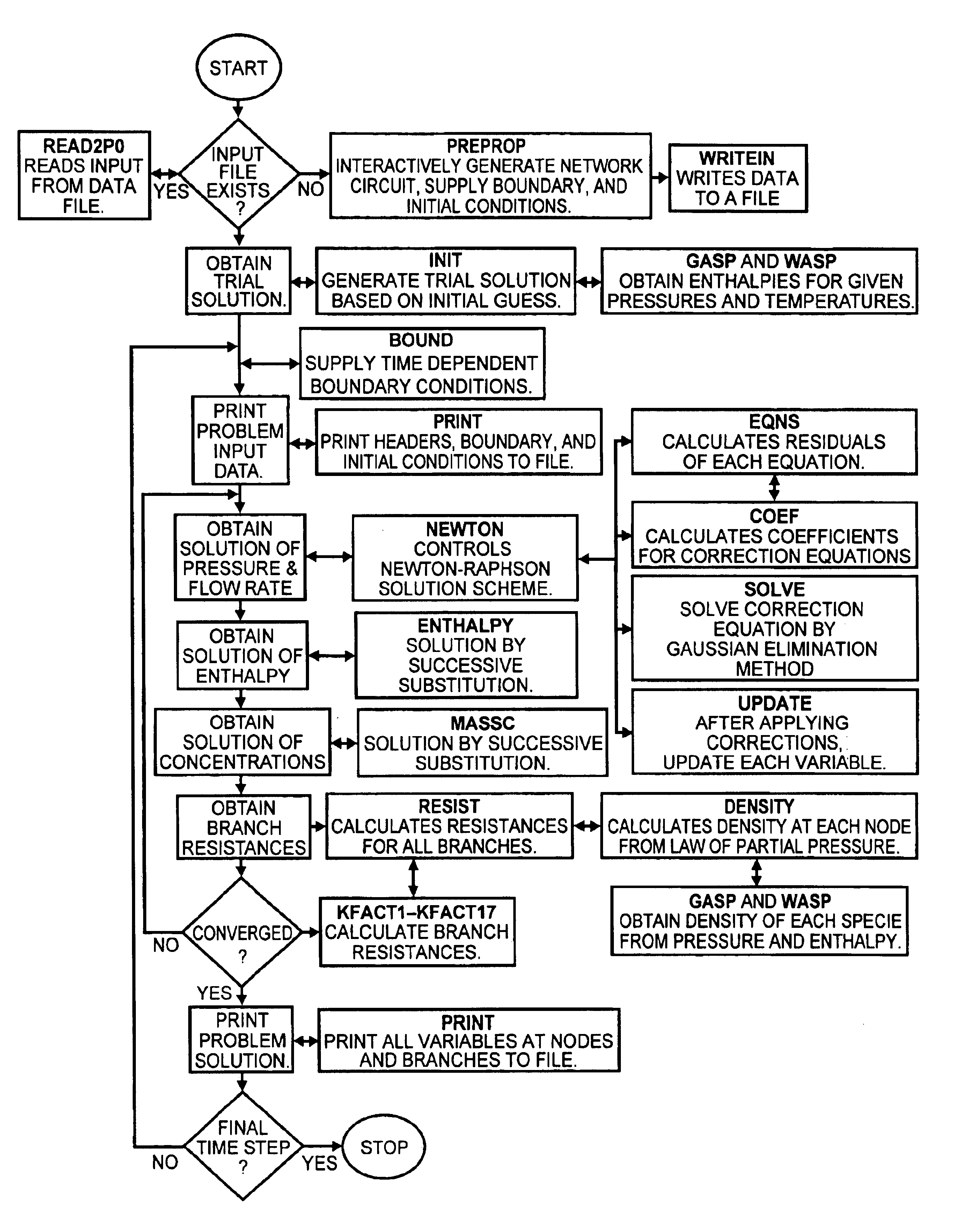
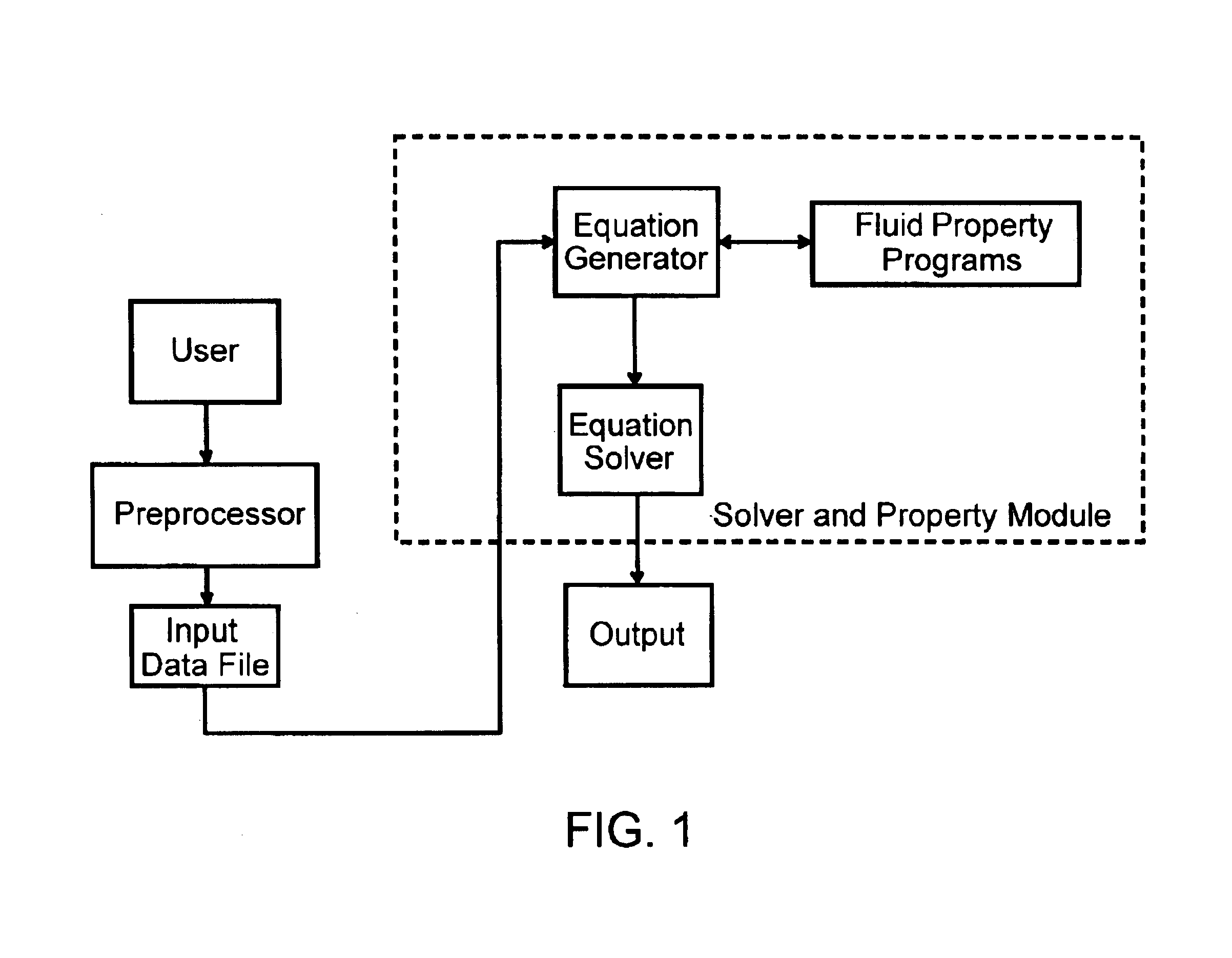
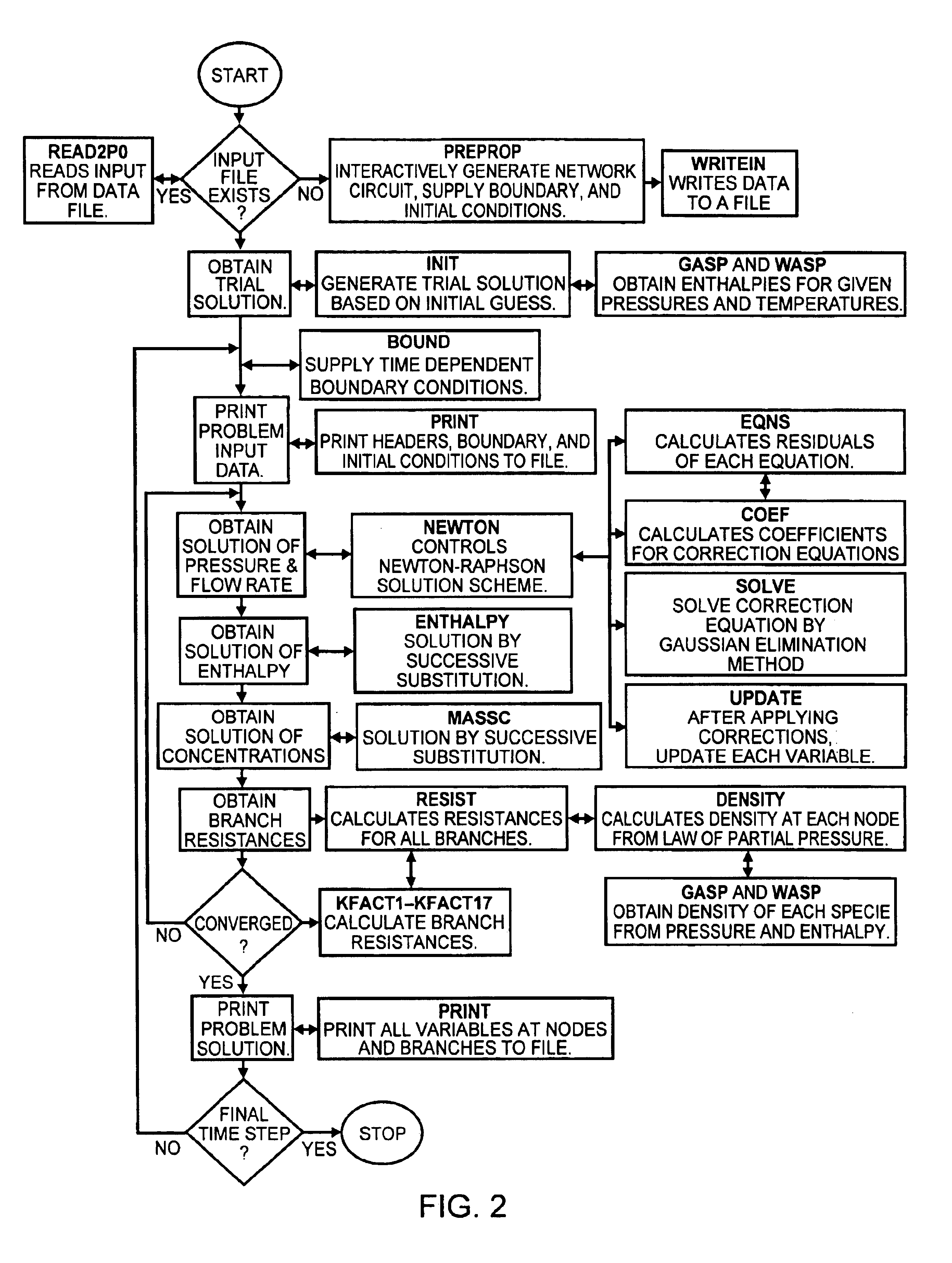
A general purpose program implemented on a computer analyzes steady state and transient flow in a complex fluid network, modeling phase changes, compressibility, mixture thermodynamics and external body forces such as gravity and centrifugal force. A preprocessor provides for the interactive development of a fluid network simulation having nodes and branches. Mass, energy, and specie conservation equations are solved at the nodes, and momentum conservation equations are solved in the branches. Contained herein are subroutines for computing "real fluid" thermodynamic and thermophysical properties for 12 fluids, and a number of different source options are provided for modeling momentum sources or sinks in the branches. The system of equations describing the fluid network is solved by a hybrid numerical method that is a combination of the Newton-Raphson and successive substitution methods. Application and verification of this invention are provided through an example problem, which demonstrates that the predictions of the present invention compare most reasonably with test data.

Description

ORIGIN OF THE INVENTIONThe invention described herein was made in the performance of work under a NASA Contract and is subject to the provisions of Section 305 of the National Aeronautics and Space Act of 1958, as amended, Public Law 85-568 (72 Stat. 435; 42 USC 2457).1. Field of the InventionThe present invention relates generally to steady state and transient flow in a complex fluid network. It relates in particular to a program implemented on a computer for analyzing steady state and transient flow in a complex fluid network to provide modeling of phase changes, compressibility, mixture thermodynamics, and external body forces.2. Description of Related ArtA fluid flow network consists of a group of flow branches, such as pipes and ducts, that are joined together at a number of nodes. They can range from simple systems consisting of a few nodes and branches to very complex networks containing many flow branches, simulating valves, orifices, bends, pumps and turbines. In the analys...

Claims


Application Information

Patent Timeline
IPC IPC(8): G06G7/48G06G7/00G05B17/02G06F17/50
CPCG05B17/02G06F17/5009G06F2217/16G06F2217/80G06F2111/10G06F2119/08G06F30/20
Inventor MAJUMDAR, ALOK KUMARBAILEY, JOHN W.SCHALLHORN, PAUL ALANSTEADMAN, TODD E.
Owner NASA
Learn More