
Triple-phase nano-composite steels

a technology of nano-composite steels and nano-composites, which is applied in the field of steel alloys, can solve the problems of limiting toughness of carbides

Inactive Publication Date: 2004-06-08
MMFX STEEL CORP OF AMERICA +1
View PDF9 Cites 27 Cited by
  • Summary
  • Abstract
  • Description
  • Claims
  • Application Information

AI Technical Summary

Problems solved by technology

Alloys intended for use in certain environments require higher strength and toughness, and in general a combination of properties that are often in conflict, since certain alloying elements that contribute to one property may detract from another.
In certain alloys, the autotempered carbides add to the toughness of the steel while in others the carbides limit the toughness.

Method used


Image

  • Triple-phase nano-composite steels
  • Triple-phase nano-composite steels
  • Triple-phase nano-composite steels

Examples


Embodiment Construction

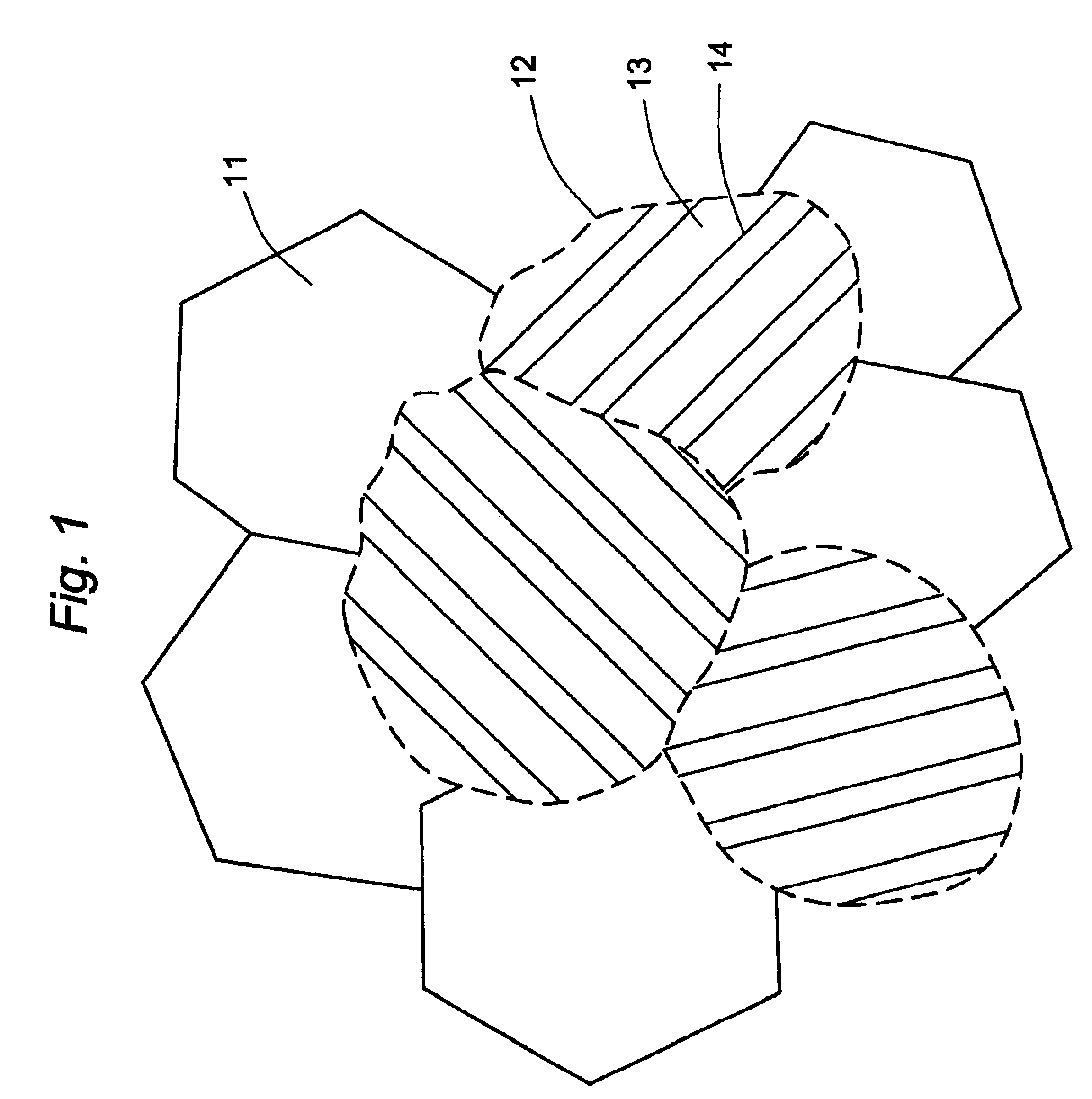
The triple-phase crystal structure of this invention thus contains two types of grains--ferrite grains and martensite-austenite grains--fused together in a continuous mass in which the martensite-austenite grains contain martensite laths that have the dislocated lath structure. The individual grain size is not critical and can vary widely. For best results, the grain sizes will generally have diameters (or other appropriately characteristic linear dimension) that fall within the range of about 2 microns to about 100 microns, or preferably within the range of about 5 microns to about 30 microns. Within the martensite-austenite grains, the martensite laths are generally from about 0.01 micron to about 0.3 micron in width (adjacent laths separated by thin austenite films), and preferably from about 0.05 micron to about 0.2 micron. The amount of ferrite phase relative to the martensite-austenite phase may also vary widely and is not critical to the invention. In most cases, however, bes...


PUM

PropertyMeasurementUnit
temperatureaaaaaaaaaa
dimensionaaaaaaaaaa

Abstract

Carbon steels of high performance are disclosed that contain a three-phase microstructure consisting of grains of ferrite fused with grains that contain dislocated lath structures in which laths of martensite alternate with thin films of austenite. The microstructure can be formed by a unique method of austenization followed by multi-phase cooling in a manner that avoids bainite and pearlite formation and precipitation at phase interfaces. The desired microstructure can be obtained by casting, heat treatment, on-line rolling, forging, and other common metallurgical processing procedures, and yields superior combinations of mechanical and corrosion properties.

Description

1. Field of the InventionThis invention resides in the field of steel alloys, particularly those of high strength, toughness, corrosion resistance, and cold formability, and also in the technology of the processing of steel alloys to form microstructures that provide the steel with particular physical and chemical properties.2. Description of the Prior ArtSteel alloys of high strength and toughness and cold formability whose microstructures are composites of martensite and austenite phases are disclosed in the following United States patents, each of which is incorporated herein by reference in its entirety:U.S. Pat. No. 4,170,497 (Gareth Thomas and Bangaru V. N. Rao), issued Oct. 9, 1979 on an application filed Aug. 24, 1977U.S. Pat. No. 4,170,499 (Gareth Thomas and Bangaru V. N. Rao), issued Oct. 9, 1979 on an application filed Sep. 14, 1978 as a continuation-in-part of the above application filed on Aug. 24, 1977U.S. Pat. No. 4,619,714 (Gareth Thomas, Jae-Hwan Ahn, and Nack-Joon ...

Claims


Application Information

Patent Timeline
Patent Type & Authority Patents(United States)
IPC IPC(8): C22C38/02C22C38/18C22C38/08C21D1/19C21D1/18C21D6/00C22C38/00C22C38/04
CPCC22C38/02C22C38/08C22C38/18C21D1/185C21D1/19C21D2201/00C21D2211/001C21D2211/005C21D2211/008
Inventor KUSINSKI, GRZEGORZ J.POLLACK, DAVIDTHOMAS, GARETH
Owner MMFX STEEL CORP OF AMERICA
Learn More