
Unbalanced gyroscopic apparatus for producing unidirectional thrust

a gyroscopic apparatus and unbalanced technology, applied in the direction of machines/engines, cosmonautic vehicles, gearing, etc., can solve the problems of complex relay and switching systems, visible wobble of the spin axis, and limited recovery of space shuttles to direct launch of low-orbit space vehicles

Inactive Publication Date: 2004-06-08
NEFF RUPERT T
View PDF7 Cites 19 Cited by
  • Summary
  • Abstract
  • Description
  • Claims
  • Application Information

AI Technical Summary

Benefits of technology

"The invention is about using an unbalanced gyroscopic apparatus to produce unidirectional thrust without interaction with gas, liquid, or solid mass and without the use of propellants. The technical effects of this invention include the ability to produce a stable spinning axis in a gyroscopic system without the need for a mass notch or a propellant, and the use of a laboratory model to demonstrate the feasibility of unidirectional thrust pulses. The invention also addresses the limitations of existing action reaction propellant-burning engines and air-breathing jet engines, which require costly and complex fuel and launch facilities, and the limitations of space-based communication and navigation systems, which require complex modeling of rapidly changing ionosphere delays and are stressed with the employment of oil products with inefficient propulsion devices."

Problems solved by technology

If a mass notch is removed from the rim at radius R in this balanced spinning gyroscopic system, an unbalanced spinning system results and a visible wobble of the spin axis is perceived.
However, a laboratory model has been constructed with the two stable unbalanced weight states as described using a pair of weights, each 0.2 ounces, attached to each other and to a one-inch radius spin plane such that they can slide along the spin-plane diameter.
Limited fuel capacity dictates that space-borne bodies must be constrained to the long-range orbits and velocities that are consistent with the local gravity environment.
Low-altitude satellite orbits are in use, but the satellites are fast moving and require complex relay and switching systems to achieve gapless data and voice exchanges.
Space Vehicle Problems.
The recoverable Space Shuttle is limited to direct launch of low-orbit space vehicles, and requires costly expenditures of fuel, special launch facilities, and personnel resources to launch satellites, repair satellites, and maintain space stations.
High risks are always present during launch, and high-speed, powerless returns to Earth require costly participation by large, cooperative global control tracking stations for success.
Space-based Communications and Navigation System Problems.
The transmission ranges of synchronous orbit satellites are also not practical for voice telephone traffic due to long delays between transmit and receive exchanges.
High-altitude, 12-hour orbit satellites, such as the Global Positioning System (GPS) for navigation, require complex modeling of rapidly changing ionosphere delays that cause degradation in ranging accuracies that limit precision to 300 feet instead of the few inches possible with sub-ionosphere altitude satellites.
Terrestrial Transportation Problems.
Both surface and air traffic densities are extreme due to the constraints imposed by the airlift-dependent aircraft and the road-bound automobile.
The Earth's natural resources are being stressed with the employment of oil products with inefficient propulsion devices.
Airports to support forward flying air dependent aircraft are extremely inefficient considering that the direct path from home A to home or city B requires travel to / from airports at locations C and D, and usually routing via location E.
Large Space System Problems.
Space-borne gyroscopic systems, such as space stations, asteroids, moons, and planets, are beyond our capability to move or propel in space because mass propellant weights are not practical.
There is no place to stand and conventional thrust methods are not currently practical.
(a) to provide an unbalanced gyroscopic apparatus to produce unidirectional thrust using only a rotating apparatus powered by standard electric rotational power sources;
(b) to provide an unbalanced gyroscopic apparatus to produce unidirectional thrust using a rotating gyroscopic apparatus with control of changing stable unbalanced weight states every 180 degrees of rotation; and
(c) to provide an unbalanced gyroscopic apparatus to produce unidirectional thrust without interacting with terrestrial gas, liquid, or solid mass or explosive action / reaction propellants;

Method used


Image

  • Unbalanced gyroscopic apparatus for producing unidirectional thrust
  • Unbalanced gyroscopic apparatus for producing unidirectional thrust
  • Unbalanced gyroscopic apparatus for producing unidirectional thrust

Examples


Embodiment Construction

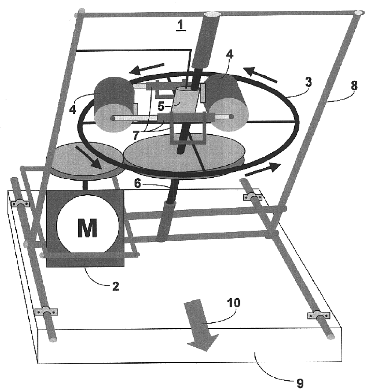
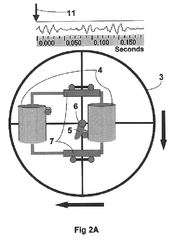
A preferred embodiment of the unbalanced gyroscopic apparatus for producing unidirectional thrust is illustrated in the FIG. 1 overview. The invention incorporates timed control of stable, unbalanced weight states in an unbalanced gyroscopic apparatus changing weight positions slidably along a spin-plane diameter path every 180 degrees of rotation. This action results in a change in momentum of the weights 4 on the spin plane 3 resulting in a reaction thrust of the spin axis 6 in the thrust direction 10. The invention fully assembled 1 and attached to a body 9 to receive thrust is shown in FIG. 1. The elements of the apparatus include: a motor element 2, a spin-plane element 3, a weight-pair element 4, a change-state element 5, a spin axis 6, a spin-plane frame element 7, and an assembly frame element 8. The assembly frame element is attached to a body to receive unidirectional thrust 9 in a thrust direction 10.

In FIGS. 2A-2D, the detail sequence producing unidirectional thrust at t...


PUM


Abstract

An unbalanced gyroscopic apparatus is disclosed for producing unidirectional thrust without having to interact with an external gas, liquid, or solid mass. The technique is based on the controlled transitions of an unbalanced spinning mass between two stable unbalanced weight states resulting in a net unidirectional thrust at the spin axis. In one existing embodiment, an apparatus with an attached body can be propelled up a planar incline "sliding" uphill against terrestrial gravity. In another embodiment, multiple pairs of synchronized and mirror-image, unbalanced gyroscopic assemblies are combined as one apparatus and attached to a body with the potential to propel it in any direction, including defeating gravity completely without interaction with gas, liquid, or solid mass or without use of propellants.

Description

1. Field of the InventionThis invention relates generally to propulsion and specifically to the use of an unbalanced gyroscopic apparatus to produce unidirectional thrust without interaction with gas, liquid, or solid mass and without the use of propellants.2. Description of Prior ArtPhysics of a rotational gyroscopic system. This invention is based on the general known parameters of a spinning gyroscopic system. Whether a one-inch radius toy or a precision navigation gyroscope, the gyroscopic system commonly employs a perfectly balanced spinning mass centered on a spin axis. In this case, a balanced spinning mass experiences a centrifugal force outward in line with the radius of the spinning mass about the spin axis. Centrifugal force on a spinning mass is a well-established quantitative parameter. An element of mass m at radius R on a spinning gyroscopic system rotating at an angular velocity of omega=2*Pi*revolutions per second experiences a centrifugal force F=m*omega.sup.2 *R d...

Claims


Application Information

Patent Timeline
Patent Type & Authority Patents(United States)
IPC IPC(8): B64G1/22B64G1/40B64C39/00F03G3/08F03G3/00
CPCB64C39/001F03G3/08B64G1/409Y10T74/18528B64C29/0008G01C19/02
Inventor NEFF, RUPERT THEODORE
Owner NEFF RUPERT T
Learn More