
Method of attaching a cladding to a vehicle

a technology of cladding and vehicle, which is applied in the direction of roofs, mechanical equipment, transportation and packaging, etc., can solve the problems of plastic and metal being incompatible for welding, plastic and metal having different thermal expansion rates, and certain plastic panels having relatively high hydroscopic growth rates

Inactive Publication Date: 2004-04-20
DECOMA EXTERIOR TRIM
View PDF9 Cites 54 Cited by
  • Summary
  • Abstract
  • Description
  • Claims
  • Application Information

AI Technical Summary

Benefits of technology

"The present invention provides a method for attaching plastic panels to a vehicle substrate that allows for relative expansion and contraction movement of the panel while securely retaining it to the vehicle. The method involves the use of a bracket, double-sided adhesive tape, retainers, and a secondary retainer. The plastic panel has a support flange and a reference nodule for positioning the bracket. The bracket has a reference notch and a reference nodule positioning it relative to the panel. The plastic panel is mounted on the bracket using a double-sided adhesive tape that allows for expansion and contraction movement of the panel. The method allows for easy attachment of plastic panels to the vehicle substrate while maintaining their shape and appearance."

Problems solved by technology

Attachment of plastic panels to the metal substrate of the vehicle poses several problems.
First, plastic and metal are incompatible for welding.
Second, plastic panels must be mounted without distortion as such distortion is visible.
Third, plastic and metal have different rates of thermal expansion.
Fourth, certain plastic panels have relatively high rates of hydroscopic growth in conditions of high humidity.
The plastic panel attachment methods of the prior art have not been completely satisfactory.
In other plastic panels, complicated moldings are required for the fasteners which result in an increase incidence of sink marks on the front face of the panel.

Method used


Image

  • Method of attaching a cladding to a vehicle
  • Method of attaching a cladding to a vehicle
  • Method of attaching a cladding to a vehicle

Examples


Embodiment Construction

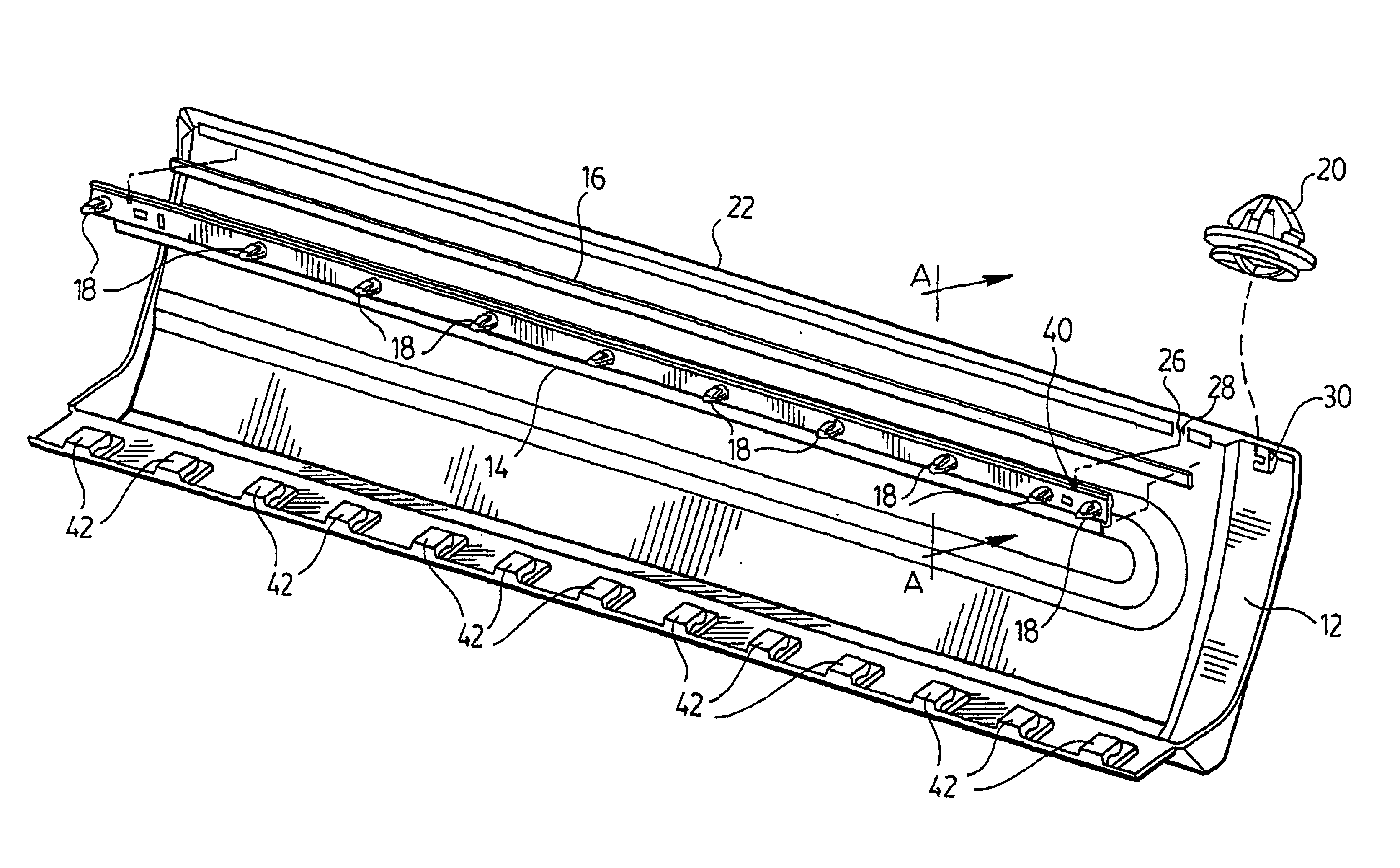
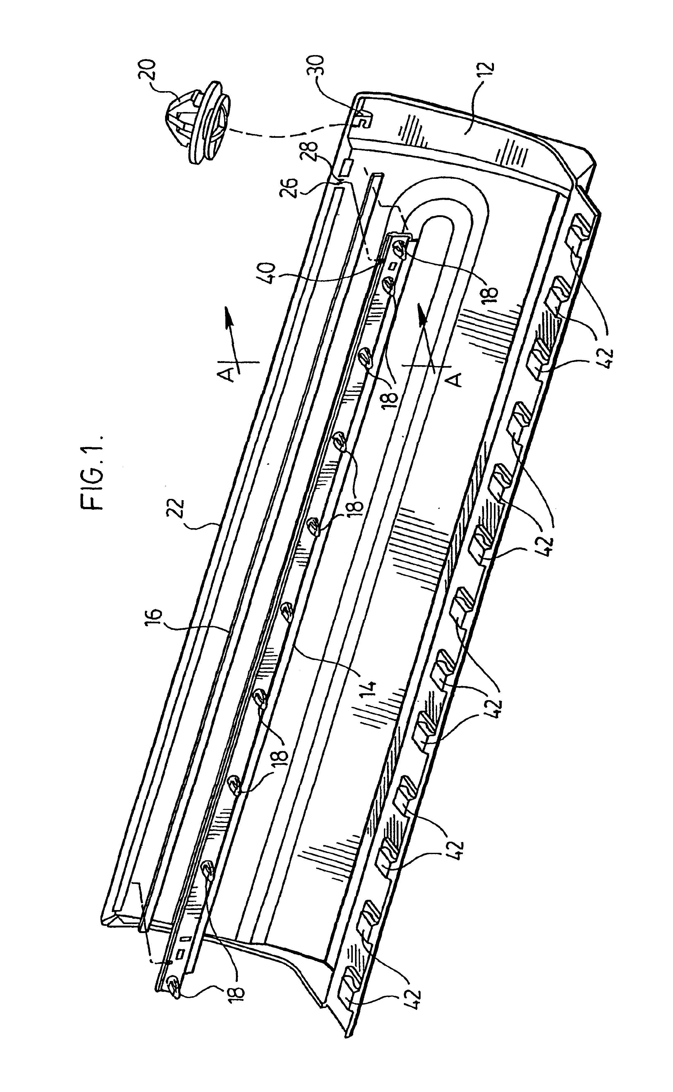
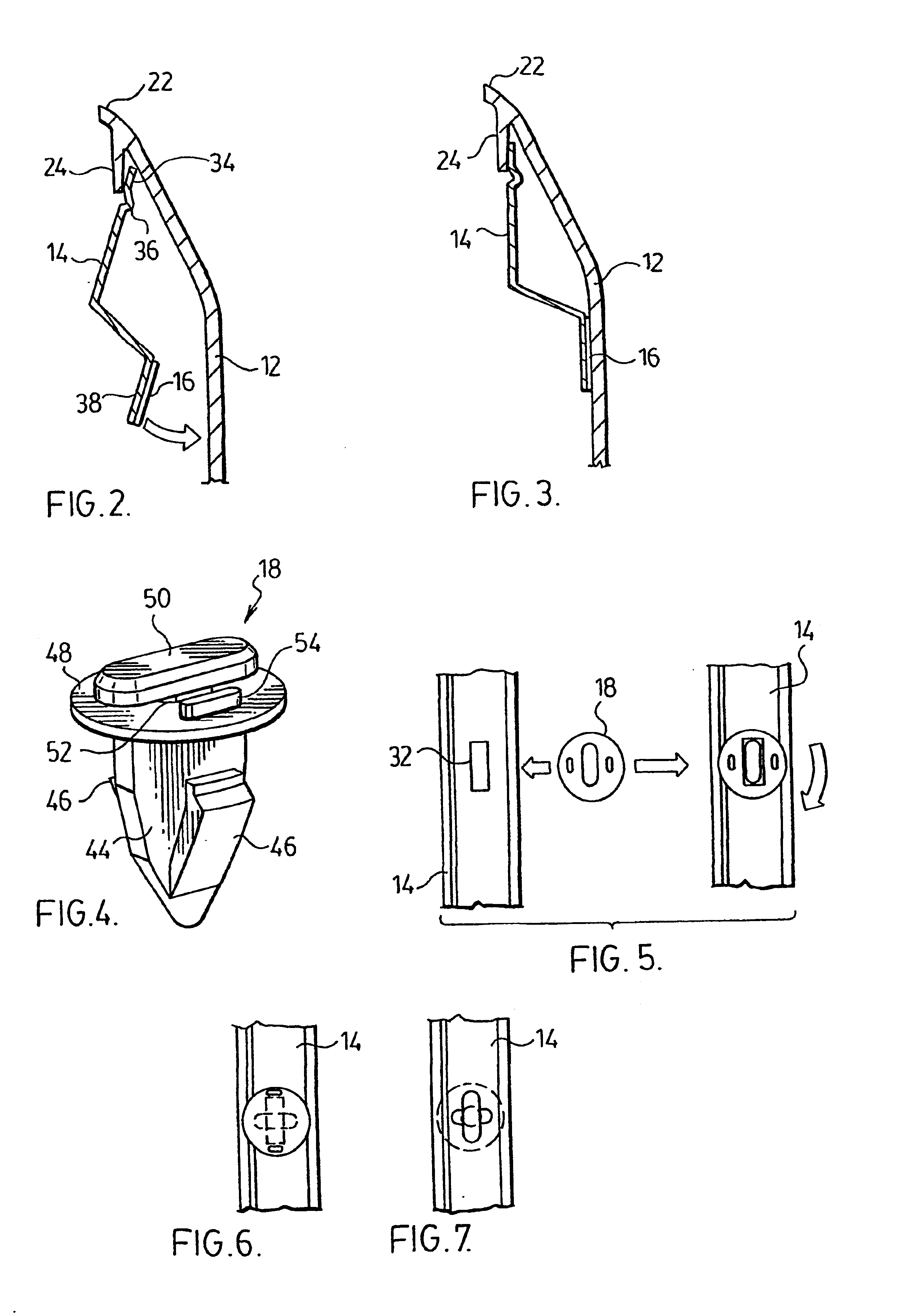
Referring to FIG. 1, a plastic panel 12 incorporating the attachment method of the present invention is illustrated. Generally, the attachment method comprises a bracket 14, a double sided strip of adhesive tape 16, a plurality of retainers 18 and a secondary retainer 20.

Plastic panel 12 has an outer contour of any desired shaping. Panel 12 can be made of any suitable plastic material, including TPO, PVC, polyurethane, polycarbonate, nylon, SMC (sheet molding compound). Panel 12 has an upper edge 22 having a molded downwardly extending support flange 24 extending longitudinally of the panel 12. The depth and thickness of the flange 24 should be less than the maximum extent allowable to mold without forming sink marks in the outer contoured surface of panel 12. Flange 24 extends substantially the length of panel 12. At one end an opening 26 is preferably provided. A reference nodule 28 is precisely positioned.

Optionally, panel 12 is provided with a dog house 30 having a keyhole for r...


PUM


Abstract

A mounting method for mounting a plastic panel (12) to a vehicle substrate provides a support flange (24) on an inner surface of the panel. A reference nodule (28) is positioned on the inner surface of the panel. An elongate bracket (14) has an upper edge (34) thereof engaging the support flange (24). The bracket (14) has a reference notch (40) engaging the reference nodule (28) positioning the bracket (14) relative to the panel (12). A plurality of retainers (18) are mounted on the bracket (14). A double-sided adhesive tape (16) has a first adhesive on a first side thereof compatible for adhesion to the bracket (14) and a second adhesive on a second side thereof compatible for adhesion to the panel (12). The first side of the adhesive tape (16) is applied to the bracket (14) and the second side is applied to the panel (12). The tape (16) allows expansion and contraction movement of the panel (12) while securely retaining the panel (12) to the vehicle substrate.

Description

This invention relates to a method for attaching cladding and other body panels onto a vehicle.BACKGROUND OF INVENTIONPlastic outer body panels have become more frequently used over metal body panels. Plastic is advantageous over metal in order to reduce vehicle weight and improve corrosion resistance Additionally, plastic panels are less susceptible to damage from minor impacts.Attachment of plastic panels to the metal substrate of the vehicle poses several problems. First, plastic and metal are incompatible for welding. Second, plastic panels must be mounted without distortion as such distortion is visible. Third, plastic and metal have different rates of thermal expansion. Fourth, certain plastic panels have relatively high rates of hydroscopic growth in conditions of high humidity.In U.S. Pat. No. 4,529,244, a plastic body panel is provided with fasteners spaced about the panel. These fasteners allow for relative sliding movement between the panel and the metal substrate. To att...

Claims


Application Information

Patent Timeline
Patent Type & Authority Patents(United States)
IPC IPC(8): B62D29/04B62D29/00B60R13/04F16B5/12F16B11/00F16B21/08F16B21/00F16B21/02F16B19/04F16B5/06
CPCB60R13/04B62D29/048F16B5/128F16B5/0657F16B5/12F16B11/006F16B19/04F16B21/02F16B21/086
Inventor LYDAN, ROBERT CHRISTOPHERMUELLER, RONALD A.KAPADIA, AMELL A.
Owner DECOMA EXTERIOR TRIM
Learn More