Fourier moire wavefront sensor

a moire wavefront and sensor technology, applied in the field of optical wavefront sensors, can solve the problems of limited sensor dynamic range, dynamic range, sensitive alignment issues, and trade-offs between diffractive effects and sensitivity,

Inactive Publication Date: 2004-04-06
STC UNM +1
View PDF19 Cites 46 Cited by
  • Summary
  • Abstract
  • Description
  • Claims
  • Application Information

AI Technical Summary

Benefits of technology

Another advantage of the present invention is that optical Fourier filtering transfers the useful information of the deflectogram (changes in fringe direction) directly to electrical signal. Certain types of morphable membrane mirrors for adaptive optics application can be driven directly from such data, obviating the need for computer-driven controls.
A further advantage is that the invention provides valuable advantages over prior wavefront detectors such as Shack-Hartmann sensors. These sensors are limited in their dynamic range because they rely on unambiguous pixel areas allocated to each lenslet in a lenslet array. To allow for unexpectedly large aberrations, the only choice is to retrofit a new lenslet array with larger lenses. The sensitivity of detection is adjustable by merely changing the distance between two gratings (ronchi rulings). This overcome another deficiency of the Shack Hartmann sensors in that these require expensive retrofitting to change sensitivity.
Yet another advantage is that the invention determines wavefront shape to a constant, i.e., the overall tilt of the wavefront remains ambiguous. Generally, this overall tilt is not considered important, as long as the shape of the wave is determined. Hence, in the present invention, the measurement is relatively Insensitive to the alignment of the beam into the device. However, tilt is precisely what is measured (not curvature) with the Shack-Hartmann device, and hence, beam alignment is a tricky issue. A beam which "wanders" is, then, most easily examined by the present invention.
Another advantage is that the invention has at least double the optical resolution of other moire techniques because the pixel spacing of the camera determines the resolution whereas in other techniques, for computation of the data to be performed, fringes have to be resolved in the image. Because it requires two pixels to resolve a single fringe (invoking the Nyquist theorem), the increase in resolution is at least twofold.
Yet another advantage is that the invention is implementable in a very compact and low cost form.

Problems solved by technology

Computer-based Fourier-transform and phase-shifting techniques are only with difficulty able to resolve and determine where fringes are, especially when fringes close into loops or branch.
Shack-Hartmann sensors (see, e.g., U.S. Pat. No. 5,936,720) are very popular for wavefront correction, but suffer from trade-offs between diffractive effects and sensitivity, dynamic range, and sensitive alignment issues.
These sensors are limited in their dynamic range because they rely on unambiguous pixel areas allocated to each lenslet in a lenslet array.
This overcome another deficiency of the Shack Hartmann sensors in that these require expensive retrofitting to change sensitivity.
However, tilt is precisely what is measured (not curvature) with the Shack-Hartmann device, and hence, beam alignment is a tricky issue.

Method used


Image

  • Fourier moire wavefront sensor
  • Fourier moire wavefront sensor
  • Fourier moire wavefront sensor

Examples


Embodiment Construction

)

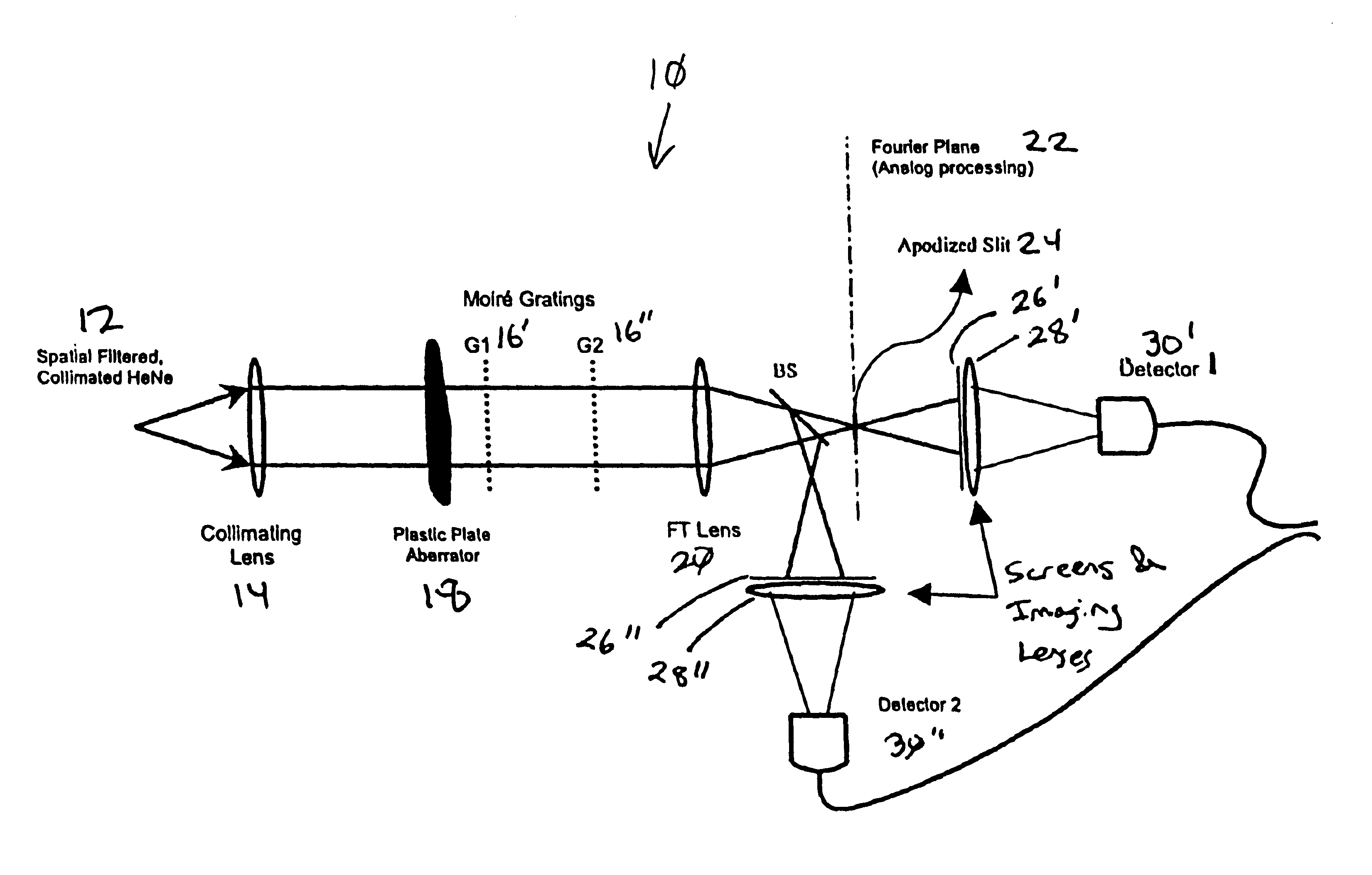
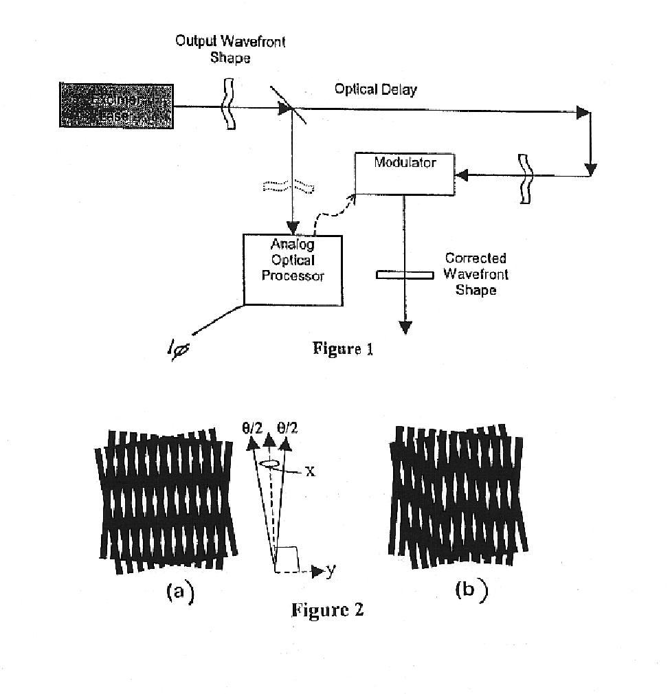
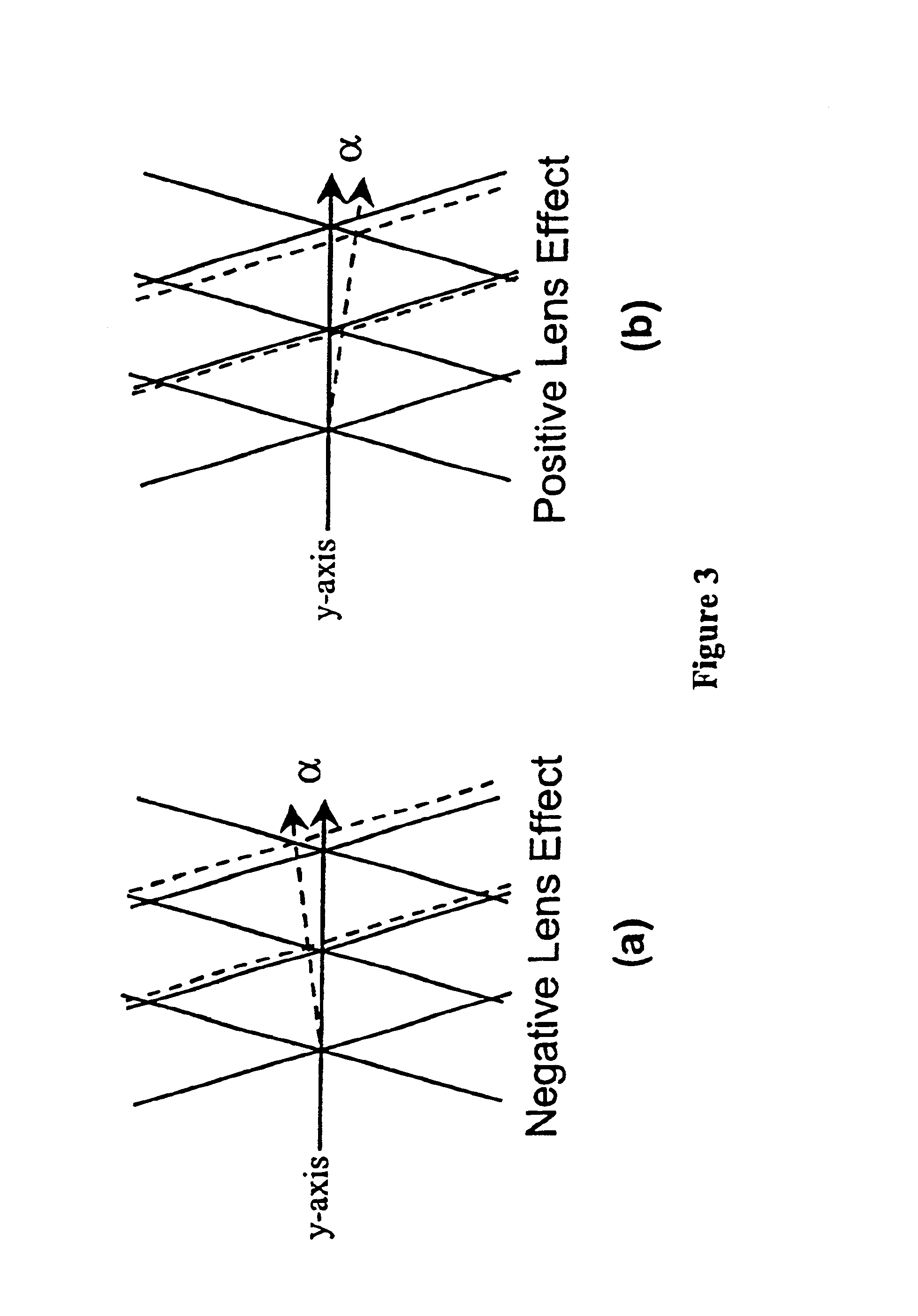
The present invention is of a Fourier moire wavefront sensor that uses moire deflectometry and the Fourier transforming properties of a lens to optically compute wavefront curvature of incident light. In a moire deflectogram, the angle of the fringes indicates the magnitude and sense of the wavefront curvature incident on the first grating. In the present invention, two gratings produce moire deflectograms. A frequency filter is placed in the Fourier plane of the lens, which has a variable transmission profile. When wavefront aberrations induce changes in the moire deflectogram, they also change the deflectogram's frequency information in a characteristic way at the Fourier plane. The broadening of particular frequency components is such that the angle of the fringes in the deflectogram is encoded as intensity information by the filter, downstream, in the image plane. Hence, wavefront curvature is encoded directly as intensity information. Optimally, 50% transmission corresponds to...


PUM


Abstract

An apparatus and method for wavefront sensing that includes: employing two moiré gratings in an optical path; optically Fourier transforming a moiré deflectogram produced by the gratings; variably transmitting the transformed moiré deflectogram; and receiving an image of the variably transmitted and transformed moiré deflectogram. The variable transmission is best accomplished by transmission filter, a transmissive optic encoding intensity information upon the moiré deflectogram as a function of fringe angle. For example, the function can be a triangular transmission function centered on the (0,0) order spatial frequency spot and oriented at 45 degrees to the y-axis. The optical Fourier transform is accomplished by a lens and the variable transmission by an apodized slit.

Description

1. Field of the Invention (Technical Field):The present invention relates to optical wavefront sensors, to optical Fourier techniques, and to moire deflectogram.2. Background Art:Typical analyses of moire deflectograms include fringe recognition, computer Fourier transformations, and phase-shifting techniques, requiring multiple shots in order to get high resolution. Computer-based Fourier-transform and phase-shifting techniques are only with difficulty able to resolve and determine where fringes are, especially when fringes close into loops or branch.Related wavefront sensor or Fourier transform technologies are disclosed in the following references: U.S. Pat. No. 6,130,419, to Neal, entitled "Fixed Mount Wavefront Sensor"; U.S. Pat. No. 5,936,720, to Neal et al., entitled "Beam Characterization by Wavefront Sensor"; U.S. Pat. No. 5,872,648, to Sanchez et al., entitled "On-Axis Spatial Light Modulators and Methods of Use"; U.S. Pat. No. 5,479,257, to Hashimoto, entitled "Method of ...

Claims


Application Information

Patent Timeline
Patent Type & Authority Patents(United States)
IPC IPC(8): G01J9/02G01J9/00
CPCG01J9/02
Inventor BERNSTEIN, AARON C.DIELS, JEAN-CLAUDE M.
Owner STC UNM
Why Eureka
Try Eureka