
Motion estimation for panoramic digital camera

a technology of panoramic digital camera and motion estimation, applied in the field of image processing, can solve the problems of wasting memory in the digital camera with redundant information, difficult to properly overlap a region between two adjacent frames of a panoramic image, and not without shortcomings

Inactive Publication Date: 2004-04-06
SONIC SOLUTIONS LLC +1
View PDF11 Cites 84 Cited by
  • Summary
  • Abstract
  • Description
  • Claims
  • Application Information

AI Technical Summary

Problems solved by technology

Although these techniques are useful, they are not without their shortcomings.
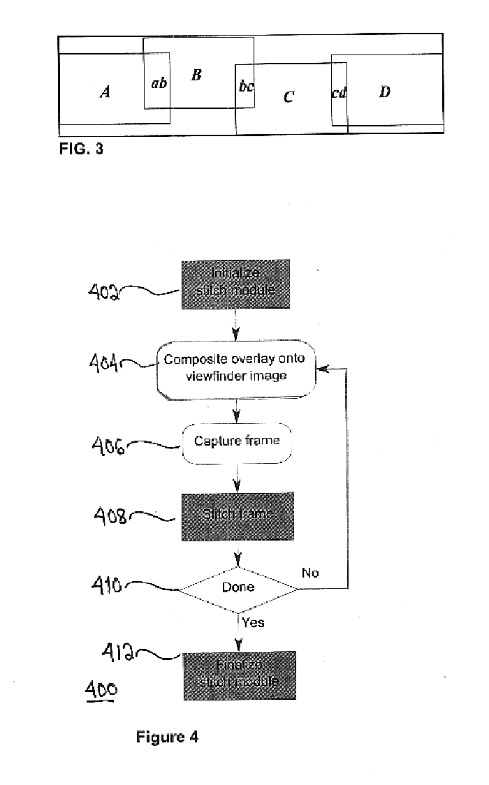
Another shortcoming of the current panoramic cameras is how difficult it is to properly overlap a region between two adjacent frames of a panoramic image.
Too much overlap results in wasting memory in the digital camera with redundant information.
Another shortcoming with current panoramic cameras is their inability to guide the user where the correct edge overlap is required for creating a panoramic picture alignment from two or more images.
Problems at the boundaries of two images include color distortion, perspective distortion, pixel adjacency and skipped pixels at the edges when joining two or more images.
Another shortcoming of the current panoramic cameras is their inability to integrate these mechanisms with other products.
The bulk, expense, and complication make these designs difficult to integrate.
Another shortcoming is the inability to easily capture two or more images to create a panoramic scene without the need for expensive computational resources in the camera and without the need for expensive position sensors.
The expense and space required for two buffers to coordinate transformations is undesirable.
This will produce a great loss of vertical resolution.
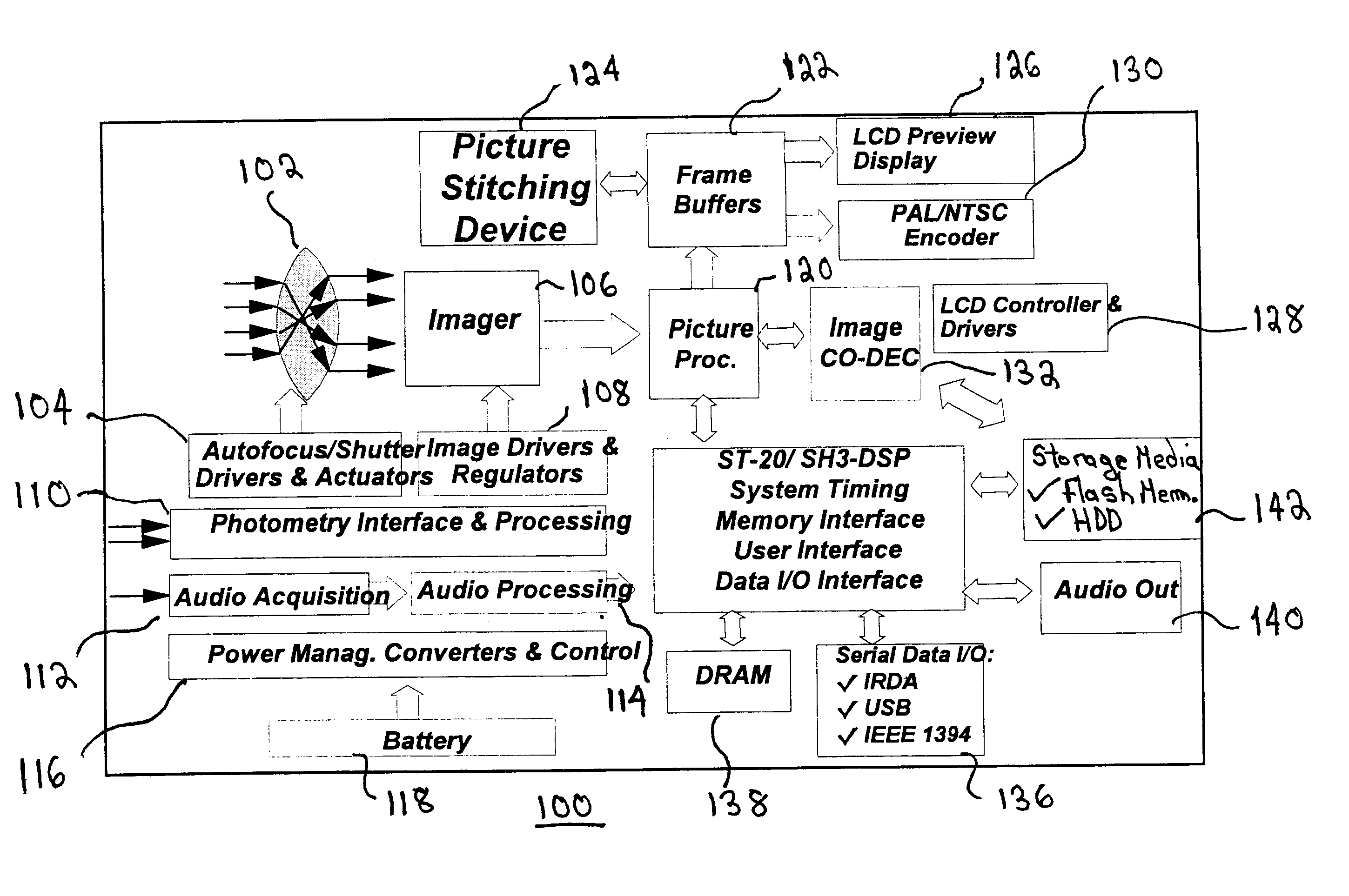
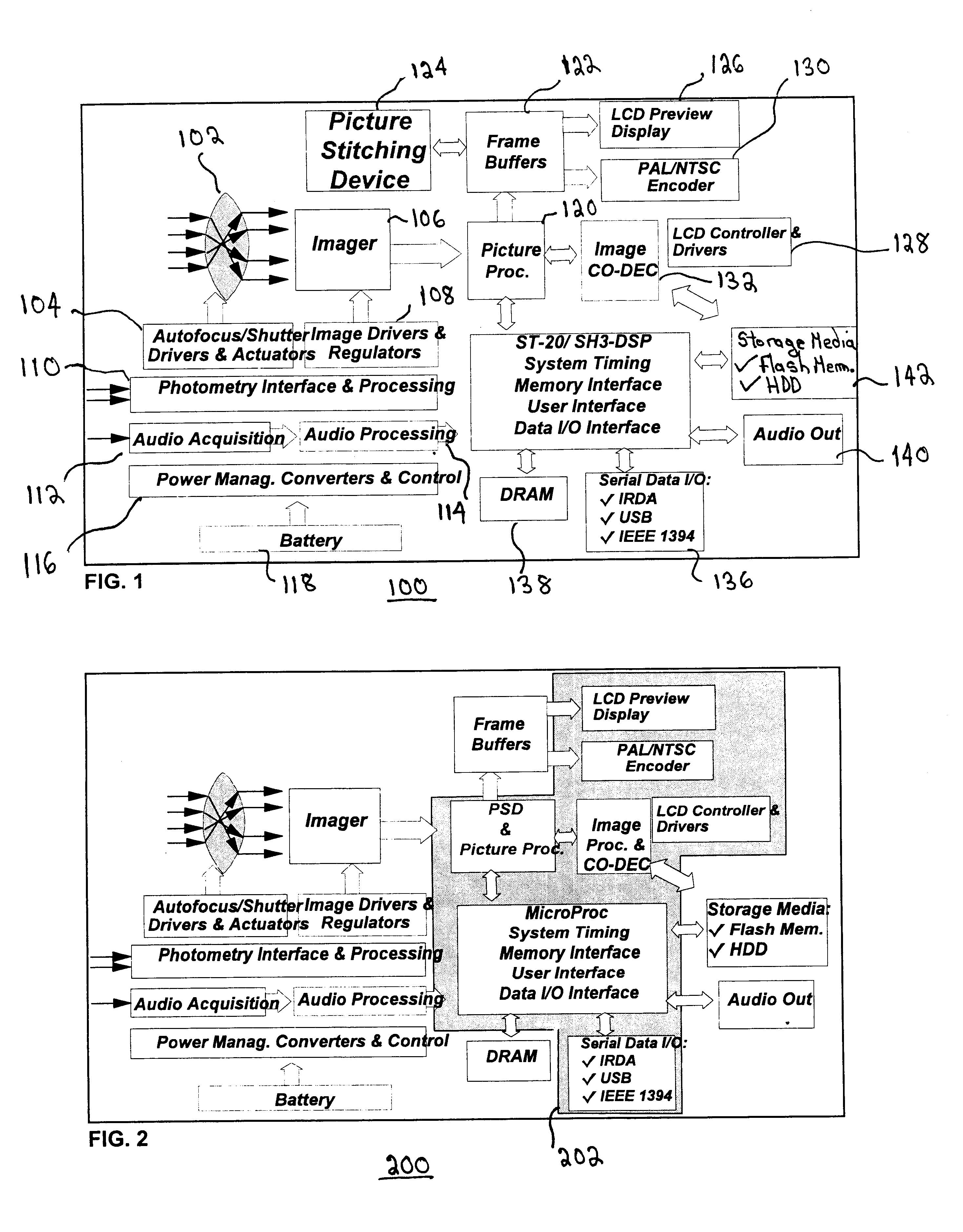
Many times, the added expense, the additional weight and the additional size of the electronic circuitry makes the camera unwieldy to carry and operate.
Moreover, the additional electronic circuitry makes the camera more expensive to manufacture.

Method used


Image

  • Motion estimation for panoramic digital camera
  • Motion estimation for panoramic digital camera
  • Motion estimation for panoramic digital camera

Examples


Embodiment Construction

However, it should be understood that these embodiments are only examples of the many advantageous uses of the innovative teachings herein. In general, statements made in the specification of the present application do not necessarily limit any of the various claimed inventions. Moreover, some statements may apply to some inventive features but not to others. In general, unless otherwise indicated, singular elements may be in the plural and visa versa with no loss of generality.

1. Glossary of Terms Used in this Disclosure

Actual Next Picture-the picture that is actually captured as the next addition to the set of pictures constituting the Panorama.

Bottom-to-Top Vertical Panorama-a Panorama captured by taking a set of pictures by rotating the camera up (from bottom to top) between each capture, with as little horizontal displacement as possible.

Current Buffer--a cylindrically warped version of the current picture.

Current Picture / Current View / Current Frame-a picture displayed on the ca...


PUM


Abstract

A method for estimating the motion between a first image and a second image in a system for creating a panoramic image from a plurality of images taken by a camera, the method comprising the steps of: downsampling a first image in a first direction and in a second direction; downsampling a second image in a first direction and in a second direction; filtering the first and the second image so as to filter out any global illumination changes between the first image and the second image; calculating a first displacement along the first direction between the first downsampled image along the first direction and the second downsampled image along the first direction; and calculating a second displacement along the second direction between the first downsampled image along the second direction and the second downsampled image along the second direction. In an alternate embodiment, a device and computer readable medium corresponding to the above method is described.

Description

1. Field of the InventionThe invention disclosed broadly relates to the field of image processing and more specifically to image processing in a digital camera for taking panoramic pictures.2. Description of the Related ArtToday, panoramic photography is accomplished in various ways. One is to use a still camera mounted on a tripod to take a succession of shots as the camera is pivoted around the tripod. In some cameras, a wider than usual strip of film is exposed with special movable optics.In other cameras, conventional format film, such as 35mm film, is masked during the exposure in the camera to provide a panoramic effect. The effect is panoramic but the whole exposure is limited by the field of view through the lens.Other techniques for creating panoramic photography include to physically cut and paste together strips of exposed film by carefully aligning boundaries between edges of film.The benefits of electronic photography have led to the growth of digital cameras, that, unl...

Claims


Application Information

Patent Timeline
Patent Type & Authority Patents(United States)
IPC IPC(8): H04N5/262H04N5/232G06T3/00G06T7/00
CPCG06T3/4038G06T7/0026H04N5/232H04N5/23238H04N5/2624G06T7/32H04N23/698H04N23/635
Inventor MANCUSO, MASSIMOLUSINCHI, EMMANUELTEO, PATRICK CHENG SAN
Owner SONIC SOLUTIONS LLC
Learn More