
Data processing device

a data processing device and data technology, applied in the field of data processing devices, can solve the problems of corrupted digital data transmitted with analogue television signals, such as teletext, vps signals or wss signals, and is only inadequately able to correct corruption caused by transmission channels by conventional data processing devices using thresholding, so as to reduce the influence of interference signals

Inactive Publication Date: 2004-03-23
THOMSON LICENSING SA
View PDF21 Cites 17 Cited by
  • Summary
  • Abstract
  • Description
  • Claims
  • Application Information

AI Technical Summary

Benefits of technology

The invention is based on the object of specifying a data processing device which guarantees a high data efficiency for the reception of digital data in an a analogue signal via transmission channels of various quality.
By using an adaptive equalizer, it is possible to correct different types of distortion, caused by the transmission channel, without the need for a training signal. The data processing device according to the invention can thus be used universally for all digital additional signals occurring in a television signal, for example.
The adaptive equalizer improves the data processing device by making it insensitive to channel interference. In addition, a data rate converter is preferably connected downstream of the adaptive equalizer, whose outputs have the correct data signals and the correct clock signal for decoding the data for a line.
To reduce the influence of interference signals, an input low-pass filter is preferably used.

Problems solved by technology

Digital data transmitted with an analogue television signal, such as Teletext, a VPS signal or a WSS signal, is corrupted by the transmission channel owing to its low-pass filtering effect, for example.
A conventional data processing device using thresholding is only inadequately able to correct corruption caused by a transmission channel.
Hence, the interpretation in the downstream decoder is incorrect or individual sections of data are not decoded, so that visible errors are shown on the screen.

Method used


Image

  • Data processing device
  • Data processing device
  • Data processing device

Examples


Embodiment Construction

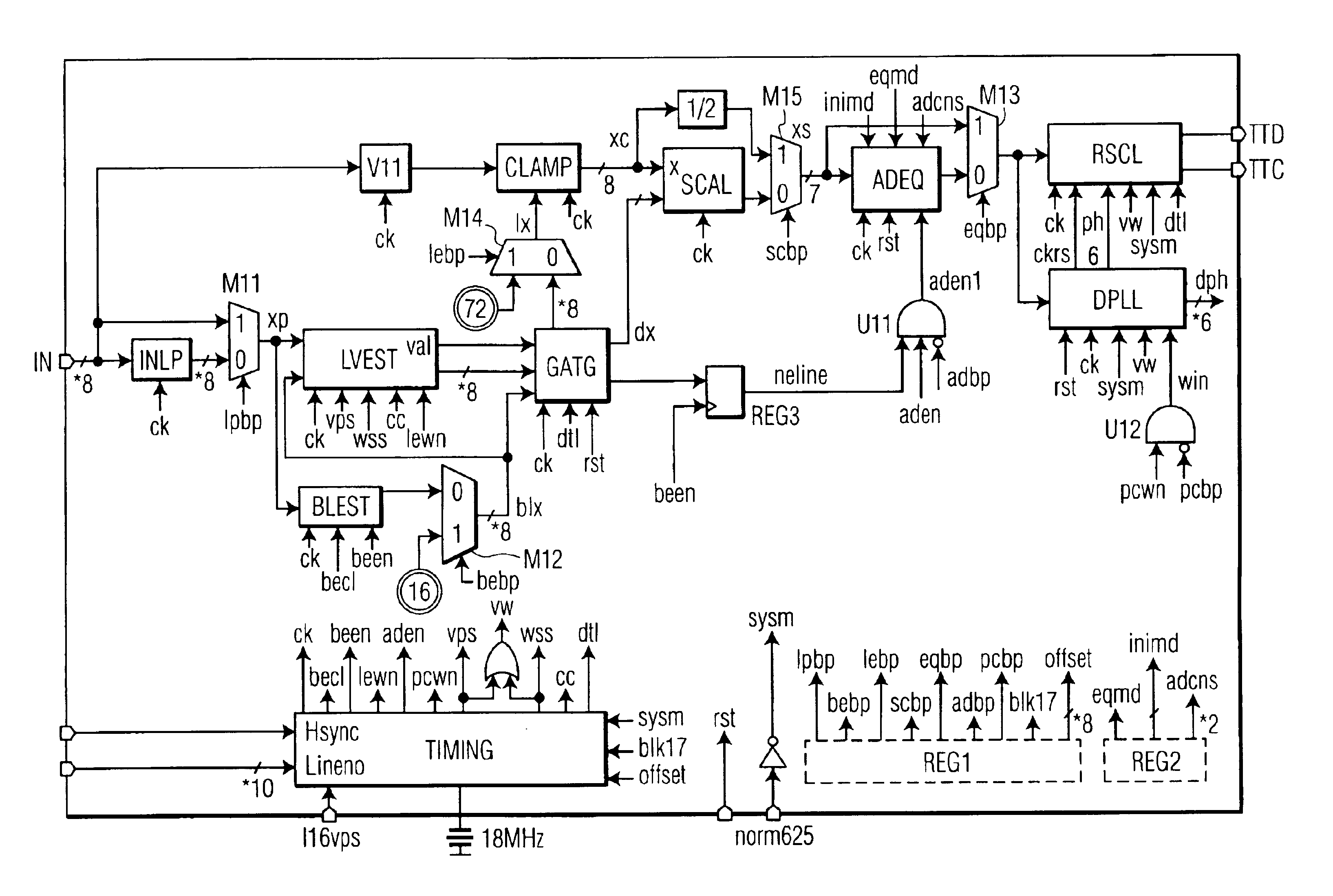
FIG. 1 shows a schematic illustration of a data processing device having an input IN, to which the digitized received data is supplied, as well as a data output TTD and a clock output TTC.

The digital input data provided has a resolution of 8 bits and a data rate of 18 MHz sampling rate for PAL / SECAM and 9 MHz for NTSC. The corresponding A / D converter is not shown. The data lines marked by a "*" are unsigned data lines.

A register REG1 can store values, depending on the decoding result, which represent possible bypass values for appropriate modules of the data processing device.

Hence, a bypass value lpdp can be used to bypass an input low-pass filter INLP through a multiplexer M11, a bypass value bebp can be used to bypass a black-level estimator BLEST through a multiplexer M12, a value lebp can be used to bypass a threshold estimator LVEST through a multiplexer M14, a value scbp can be used to bypass a scaling device SCAL through a multiplexer M15, and a value eqbp can be used to byp...


PUM


Abstract

The invention relates to a data processing device for recovering digital data which is received in an analogue transmitted signal. According to the invention, the received signal is digitized and a threshold is determined in a threshold estimator. The interference in the channel is corrected in a downstream adaptive equalizer, and a bit clock generator produces the correct sampling rate and phase for the data of a line. The threshold estimator is used to determine the mean value of an input signal for each line, and this value is then taken as the optimum decision value for sampling the data bits for this line. By using an adaptive equalizer, it is possible to correct different types of distortion, caused by the transmission channel, without the need for a training signal. The data processing device according to the invention can thus be used universally for all digital additional signals occurring in a television signal, for example.

Description

The invention relates to a data processing device for recovering digital data which is received in an analogue transmitted signal.PRIOR ARTDigital data transmitted with an analogue television signal, such as Teletext, a VPS signal or a WSS signal, is corrupted by the transmission channel owing to its low-pass filtering effect, for example. The digital data is then reconstructed in a receiver by thresholding. The output of a conventional data processing device then provides a digital data stream which is supplied to a downstream decoder for error correction, interpretation of the data and grouping the bits into bytes.A conventional data processing device using thresholding is only inadequately able to correct corruption caused by a transmission channel. Hence, the interpretation in the downstream decoder is incorrect or individual sections of data are not decoded, so that visible errors are shown on the screen. The data efficiency thus depends on the transmission channel.INVENTIONThe...

Claims


Application Information

Patent Timeline
Patent Type & Authority Patents(United States)
IPC IPC(8): H04L25/03H04L7/033H04N7/035H04L25/06H03H21/00H03L7/099H03L7/08H04L7/04H04N5/14H04B3/06H04N7/025H04N7/03
CPCH04L7/0331H04L25/03038H04L25/062H04N7/035H03H21/0012H03L7/0994H04L7/046H04L2025/03375H04L2025/03477H04L2025/03617H04L2025/03662
Inventor LIN, JINANERBAR, MAXIMILIAN
Owner THOMSON LICENSING SA
Learn More