
Optical printer with color filter and optical printing method

Inactive Publication Date: 2004-03-23
FUJIFILM CORP +1
View PDF12 Cites 5 Cited by
  • Summary
  • Abstract
  • Description
  • Claims
  • Application Information

AI Technical Summary

Benefits of technology

The color separation filter unit further includes at least one ND filter for reducing the light amount of the printing light of at least one of the single colors.
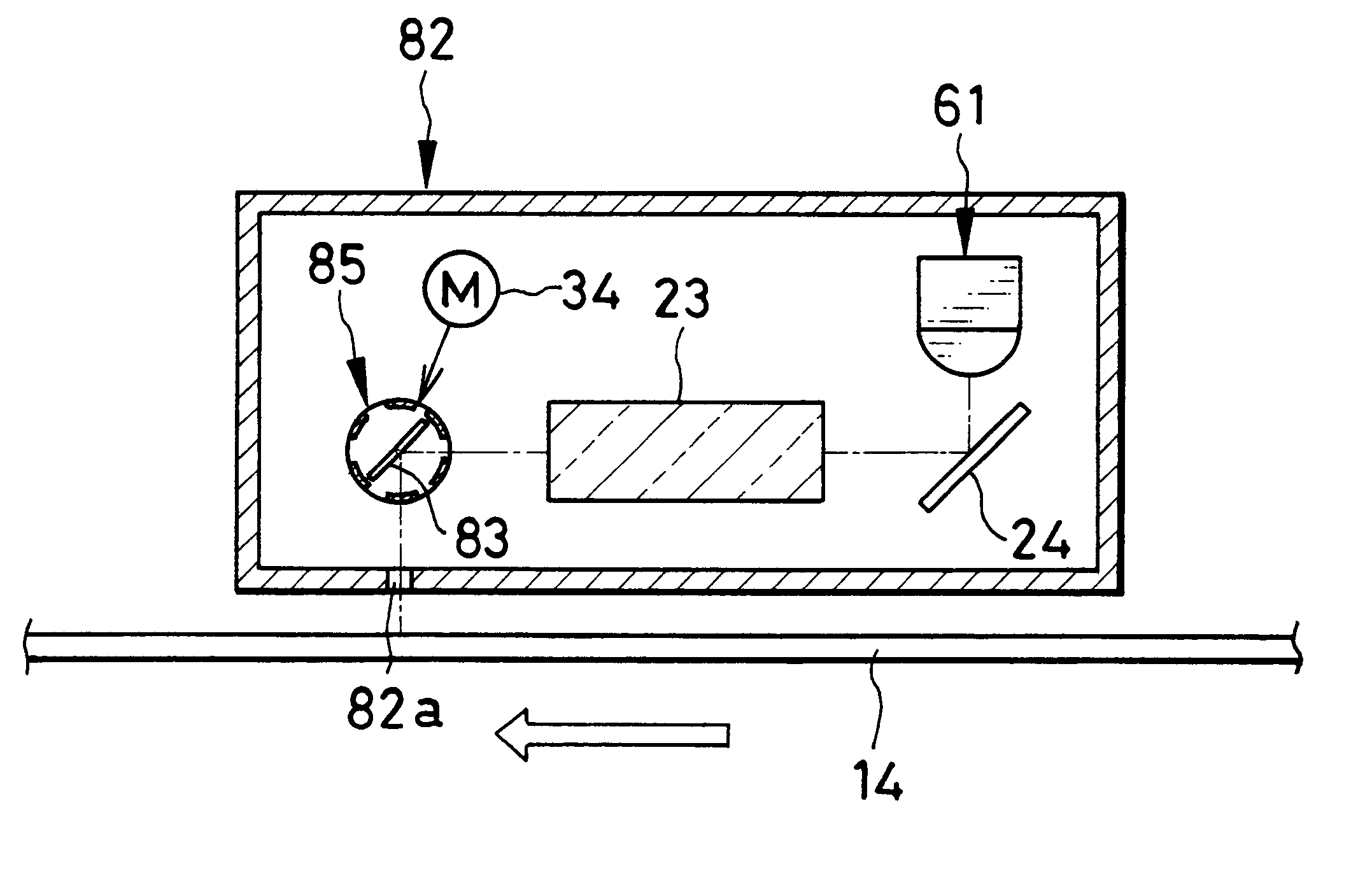
According to another aspect of the invention, an optical printer records a color image by exposing a color photosensitive material. The optical printer comprises a printing head, which includes a light source and a color separation filter unit. The color separation filter unit is disposed in a light path of light from the light source, for color separation of the light from the light source. The color separation filter unit includes plural color filters, arranged in a manner adjacent to one another in a plate shape, having selectivity of a wavelength, set in the light path sequentially, for converting the light from the light source into printing light of respectively single colors. At least one ND filter, disposed to lie on at least one of the plural color filters, for reducing the light amount of the printing light of at least one of the single colors.

Problems solved by technology

Also, a head moving mechanism is required for the printing head, and may cause the optical printer to have a considerably large size.
Furthermore, a problem of the frame-sequential printing in the full color lies in very long time required for printing, as the printing head is moved back and forth for frames of three colors.

Method used


Image

  • Optical printer with color filter and optical printing method
  • Optical printer with color filter and optical printing method
  • Optical printer with color filter and optical printing method

Examples


Embodiment Construction

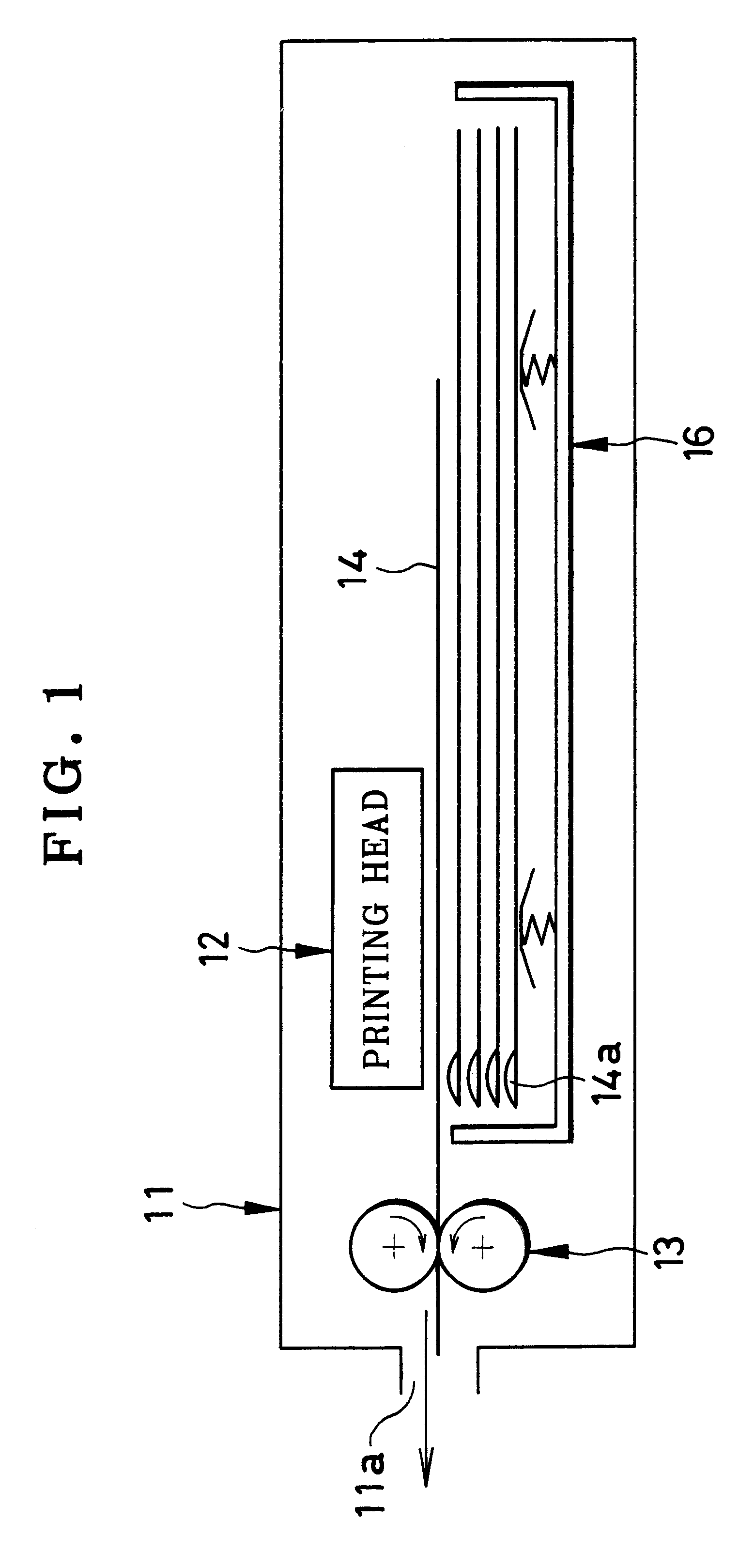
In FIG. 1, an optical printer 11 is depicted, and includes a printing head 12 and spreader rollers 13. The optical printer 11 is loaded with a cartridge 16 or instant photo film pack containing a stack of plural instant photo films 14 as color photosensitive material. The instant photo films 14 are a well-known mono-sheet type including red, green and blue sensitive layers overlaid on a support, and have a processing solution pod 14a for containing processing solution. After printing, the instant photo film 14 being exposed is squeezed by the spreader rollers 13 to break the processing solution pod 14a, from which the processing solution is spread to an exposure surface of the instant photo film 14. The instant photo film 14 is ejected through an exit slot 11a upon spreading of the processing solution. The instant photo film 14 after the ejection comes to have a positive image in the exposure surface at a lapse of one minute or a few minutes.

The printing head 12 records a color imag...


PUM


Abstract

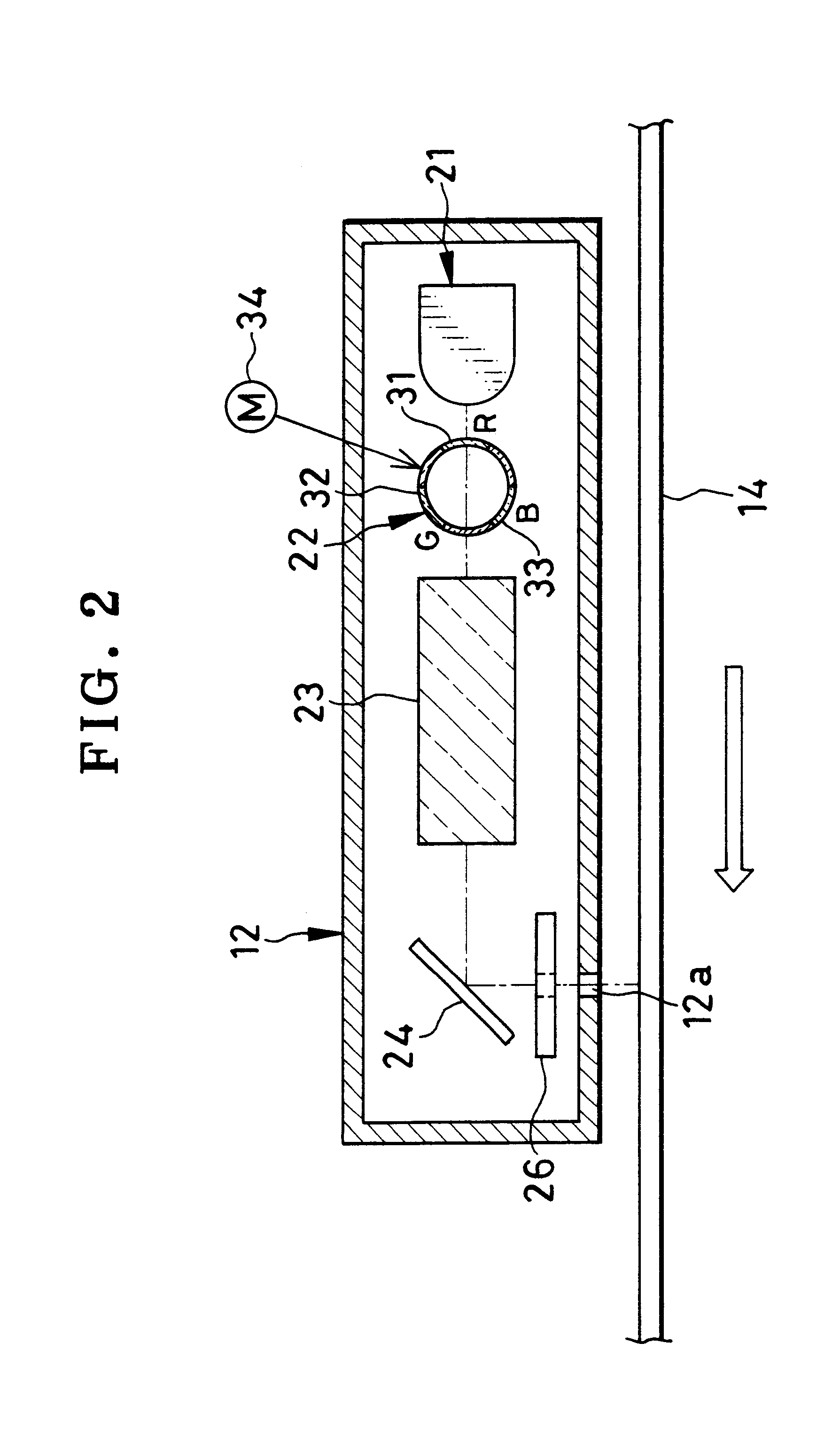
An optical printer records a color image by exposing color instant photo film extending two-dimensionally in a main scan direction and a sub scan direction. The optical printer includes a printing head, which includes a white color light-emitting element and a color separation filter unit. The color separation filter unit is disposed in a light path of white-color light from the light-emitting element, for color separation of the white-color light. The color separation filter unit has a tubular shape, has a central axis extending substantially parallel with the main scan direction, and is rotatable about the central axis. The white-color light travels through an entrance position along the light path into the color separation filter unit, out of which the light travels through an exit position along the light path. The color separation filter unit includes three color filters, arranged about the central axis, having selectivity of a wavelength, for converting the white-color light into printing light of respectively single colors. The three color filters are so disposed that a single one thereof is in the entrance position or the exit position in a manner irrespective of a rotation position with reference to the central axis. Three transparent plates are arranged alternately with the three color filters.

Description

1. Field of the InventionThe present invention relates to an optical printer with a color filter and optical printing method, and more particularly, relates to an optical printer with a color filter and optical printing method in which printing light is applied to color photosensitive material to print a color image, and in which such an image can be printed efficiently.2. Description Related to the Prior ArtAn optical printer is a known device in which printing light of plural colors is applied to color photosensitive material for printing a color image thereto. The optical printer has a printing head, which includes a light source of white light and a color separation filter unit. The color separation filter unit is constituted by plural color filters of red, green and blue colors for converting light from the light source into the printing light of the red, green and blue colors. The printing head has a length of one line included in the color image, and is disposed to extend in ...

Claims


Application Information

Patent Timeline
IPC IPC(8): B41J2/525B41J2/465B41J2/435B41J2/445G03B27/32G03B27/73G03D9/00
CPCB41J2/465B41J2/525
Inventor MIYAZAKI, TAKAOUCHIOKE, KEIZO
Owner FUJIFILM CORP
Learn More