Extruder comprising blister mechanism

a technology of a blister mechanism and an extruder, which is applied in the direction of mixing/kneading with horizontally mounted tools, clay mixing apparatus, rotary stirring mixers, etc. it can solve the problems of not being able to deal, adjustable pins and displaceable supporting elements not allowing uniform deformation over the cross section of the flow channel

Inactive Publication Date: 2004-03-16
BERSTORFF GMBH
View PDF19 Cites 8 Cited by
  • Summary
  • Abstract
  • Description
  • Claims
  • Application Information

AI Technical Summary

Benefits of technology

The invention can be realized particularly advantageously in the case of a single-screw extruder, which has a purely cylindrical extrusion space, with the result that the encircling gap at the blister is formed as an annular gap. The hydraulic pressure in the pressure chamber allows the membrane wall to deform to the respectively desired dimensions in a geometrically very uniform shape (circular shape). The desired settings can be controlled extremely quickly and easily, since all that matters is the difference in pressure between the hydraulic pressure and the pressure in the extrusion space.
A particularly advantageous embodiment of the invention in the case of a twin-screw extruder is obtained by providing a special barrel section which, instead of a spectacle-bore, has two corresponding fully cylindrical, i.e. not overlapping, longitudinal bores for the two screw shanks, these longitudinal bores of course having a smaller diameter than the respective partially cylindrical overlapping bores of the spectacle-bore. The diameter of the fully cylindrical bore preferably corresponds in each case to the root diameter of the respective screw shank, that is to say is only slightly larger than the latter. In this embodiment, in this special barrel section there is consequently a material bridge between the two longitudinal bores at the location corresponding to the interstitial region of the spectacle-bore. Respectively arranged in the surface of the longitudinal bore in this barrel section is a hydraulic pressure chamber, which is designed such that it runs all the way around in the same way as in the case of the embodiment for a single-screw extruder. This solution permits a completely uniform setting of the respective annular gap over the entire circumference. The pressure chambers of the two longitudinal bores can be partitioned off fully from each other, but may also be directly connected to each other in conducting terms.

Problems solved by technology

Until now there has been no possible way of optimizing the clearance in such a situation.
It has so far also not been possible to deal with this in an optimum way.
A disadvantage of this known device is that the adjustable pins and displaceable supporting elements do not allow uniform deformation over the cross section of the flow channel, since the introduction of the deforming forces can only ever take place in a punctiform or locally limited way.
Another disadvantage is that the thin walls of the sleeves are unavoidably deformed by the melt pressure prevailing in the flow channel counter to the force of the elements used for the adjustment.
Consequently, it is impossible for the device to be operationally used under geometrical conditions of the entirely unloaded state (zero position).
The reason for this is primarily to be seen in the fact that, because of the associated sealing problems, it is more difficult to provide a supply of hydraulic pressure medium to the pressure chamber on the screw shank than on the extruder barrel, which unlike the screw shank is completely immovable.
Since the parts of the screw shanks provided with flights have a greater outside diameter than the fully cylindrical longitudinal bores of the special barrel section, they cannot be pushed through the latter during assembly.

Method used


Image

  • Extruder comprising blister mechanism
  • Extruder comprising blister mechanism
  • Extruder comprising blister mechanism

Examples


Embodiment Construction

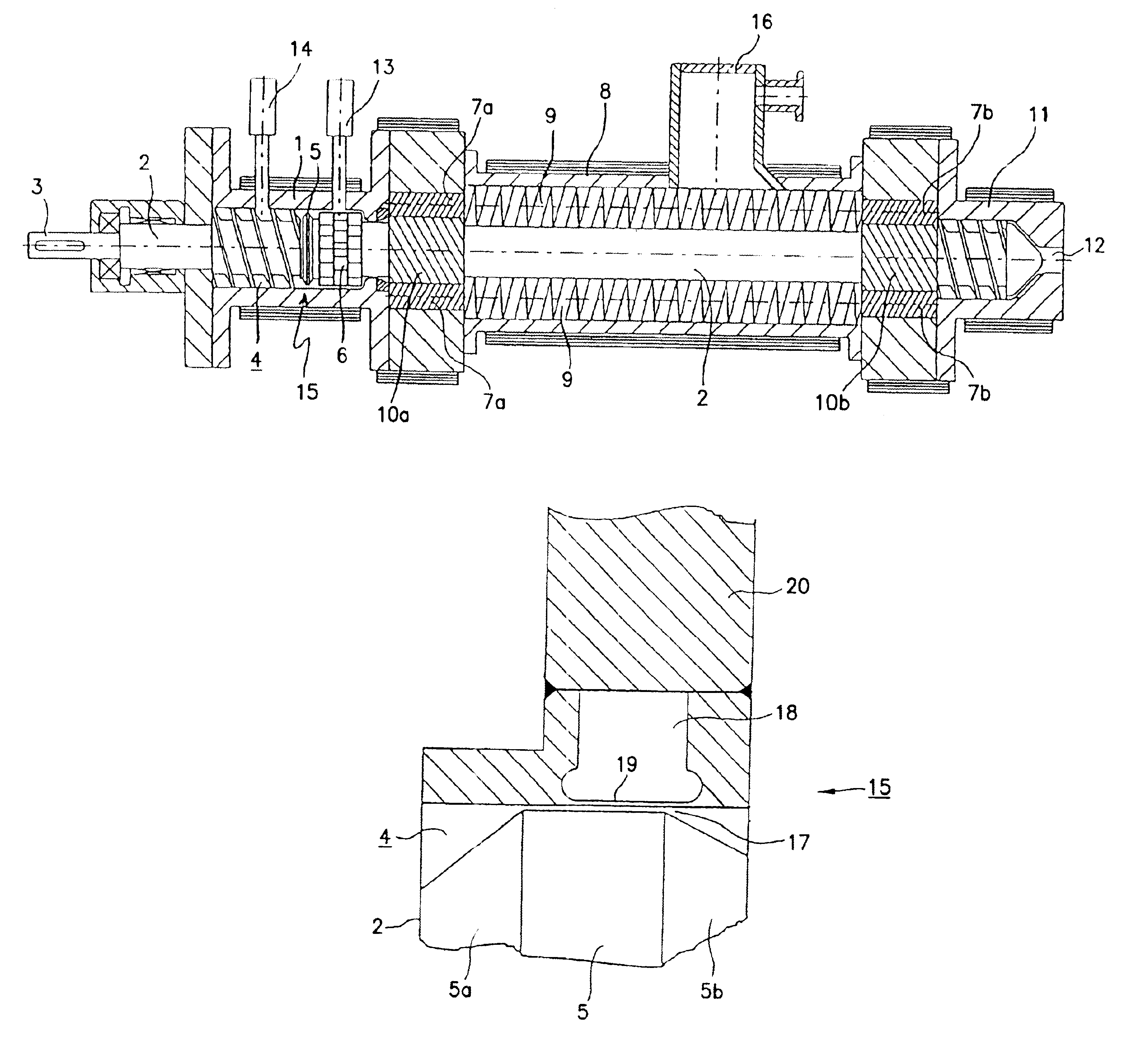
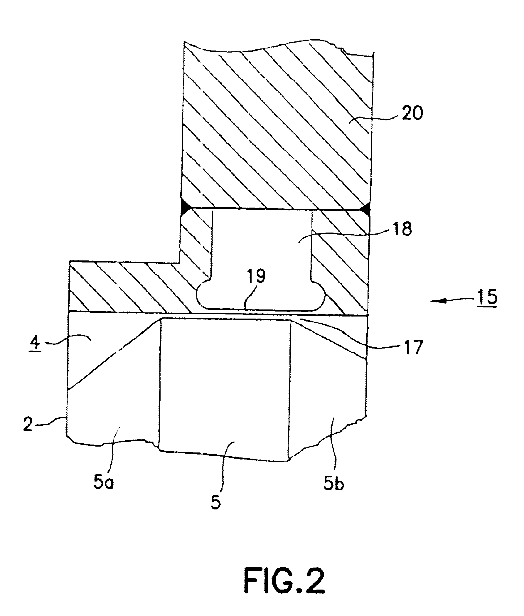
The schematic representation of the extruder in FIG. 1 shows an extruder barrel which is passed through by a screw shank 2 over virtually the entire axial length. The screw shank 2, provided with a journal 3 with fitting key, is rotationally driven by a motor (not represented) via a gear mechanism (likewise not represented). The barrel section 1 which directly adjoins the gear mechanism and the cylindrical surface of which essentially corresponds in diameter to the outside diameter of the screw of the screw shank 2 encloses a part of the extrusion space 4. The barrel section 1 is provided with a connecting piece of a melt feed 14. Consequently, the extruder represented is fed the material to be processed not in the form of granules or powder but in an already molten form. Directly following the screw of the screw shank 2 there is also arranged in the barrel section 1 a blister 15, which forms a restricted flow zone, so that the part of the extrusion space 4 lying upstream of the bli...


PUM

PropertyMeasurementUnit
Thicknessaaaaaaaaaa
Thicknessaaaaaaaaaa
Pressureaaaaaaaaaa

Abstract

An extruder for polymer melts, with an extrusion space arranged in an extruder barrel and through which at least one extruder screw shank extends so that it can be rotated by a motor. The screw shank has at least one section in the form of a cylinder casing, the extrusion space having at least one barrel section which surrounds the cylinder casing in an essentially equidistant manner to form an encircling gap as a restricted flow zone (blister), in particular to set the pressure of the melt. The clearance of the encircling gap at the restricted flow zone can be changed in a specifically selective manner by externally adjustable force, with elastic deformation of the inside surface of the extrusion space and / or of the surface of the screw shank, by a hydraulic pressure chamber provided in the region of the restricted flow zone in the wall of the barrel section and / or in the least one screw shank. The pressure chamber has on the side facing the extrusion space a considerably smaller wall thickness (membrane wall) in comparison with the wall thickness of the extrusion space. A hydraulic pressure unit supplies the force for the surface deformation.

Description

1. Field of the InventionThe invention relates to an extruder, in particular for processing polymer melts, with an extrusion space which is arranged in an extruder barrel and through which at least one extruder screw shank extends in such a way that it can be rotated by a motor, said screw shank having on it at least one section in the form of a circumferential bulge, the extrusion space having at least one barrel section which surrounds in an essentially equidistant manner the at least one extruder screw shank in the area of the at least one circumferential bulge to form an annular gap as a restricted flow zone (blister), in particular to set the pressure of the melt.2. Description of the Related ArtAn extruder of this type is disclosed by U.S. Pat. No. 4,332,481.Such a restricted flow zone formed as an encircling gap, for example as an annular gap, in the extrusion space is also referred to as a blister and serves in particular for setting the pressure of the melt processed in the...

Claims


Application Information

Patent Timeline
IPC IPC(8): B29C47/42B29C47/38B29C48/395B29C48/425B29C48/44
CPCB29C47/0871B29C47/663B29C47/42B29C47/38B29C47/0009B29C48/03B29C48/268B29C48/395B29C48/425B29C48/435B29C48/683B29C48/44B29B7/485B29B7/845B29B7/60B29B7/489B29B7/487
Inventor BEHLING, MICHAEL
Owner BERSTORFF GMBH
Why Eureka
Try Eureka