
Wind gauge

a wind gauge and wind direction technology, applied in the direction of instruments, golfing accessories, digital computer details, etc., can solve the problems of large electrical current required to maintain the self-heating resistive element, time-consuming for each measurement, and application to a portable measurement uni

Inactive Publication Date: 2004-01-27
GENERAL WIRELESS OPERATIONS +1
View PDF8 Cites 17 Cited by
  • Summary
  • Abstract
  • Description
  • Claims
  • Application Information

AI Technical Summary

Benefits of technology

"The present invention relates to a portable device and method for measuring wind speed and direction. The device includes a wind gauge with a controller and microphones that can measure wind pressure levels in different directions. The controller uses the microphones to capture wind pressure levels and compares them with pre-set threshold values to determine the wind speed and direction. The device is compact, portable, and does not require large amounts of power. The technical effect of the invention is to provide an effective tool for measuring wind speed and direction for golf club selection and swing determination."

Problems solved by technology

The common drawback in the prior art teachings for measuring wind speed and direction is in their application to a portable measurement unit.
The rotary anemometer and wind gauge need to be mounted in a fixed position, as they are relatively large and unwieldy for portable applications.
In the thermal devices, very large amounts of electrical current are required to maintain the self-heated resistive element.
Another limitation of the thermal device is that the resistive element has to be heated up before taking accurate measurement, which is time consuming for each measurement.

Method used


Image

  • Wind gauge
  • Wind gauge
  • Wind gauge

Examples


Embodiment Construction

Illustrative embodiments and exemplary applications will now be described with reference to the accompanying drawings to disclose the advantageous teachings of the present invention.

While the present invention is described herein with reference to illustrative embodiments for particular applications, it should be understood that the invention is not limited thereto. Those having ordinary skill in the art and access to the teachings provided herein will recognize additional modifications, applications, and embodiments within the scope thereof and additional fields in which the present invention would be of significant utility.

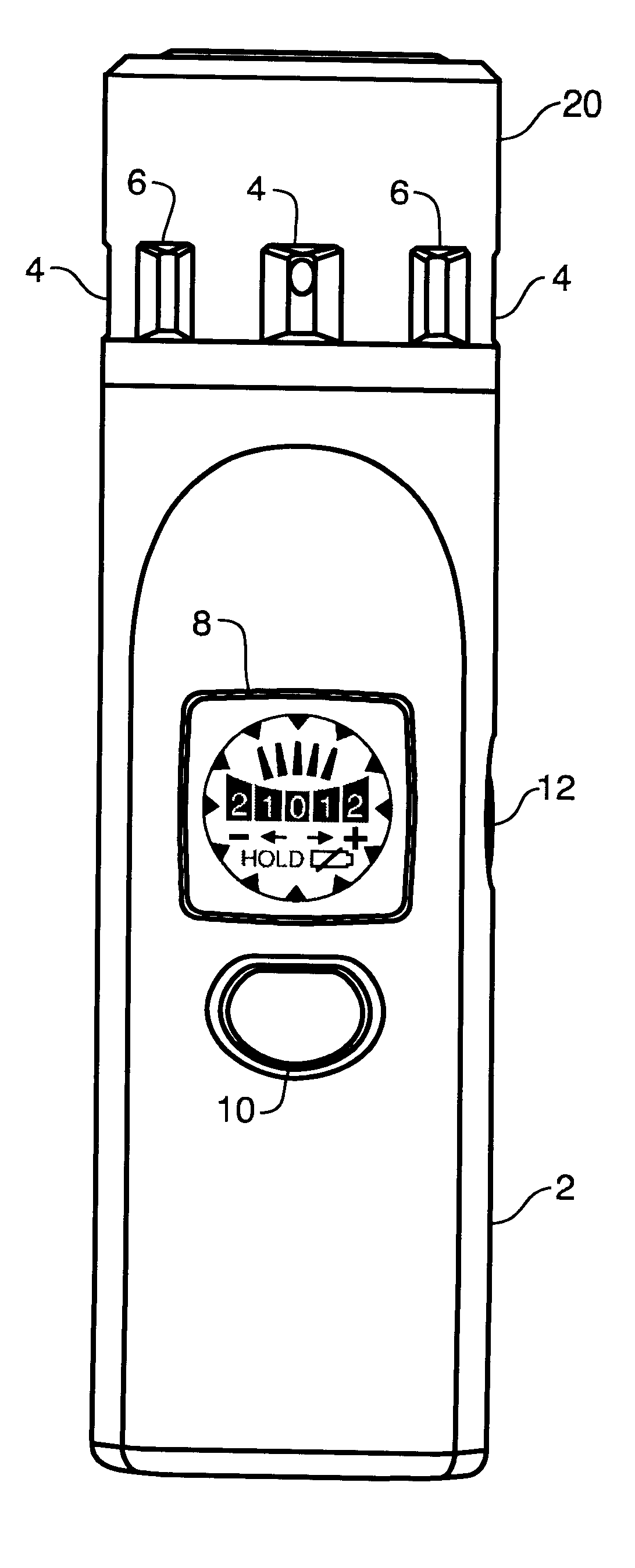
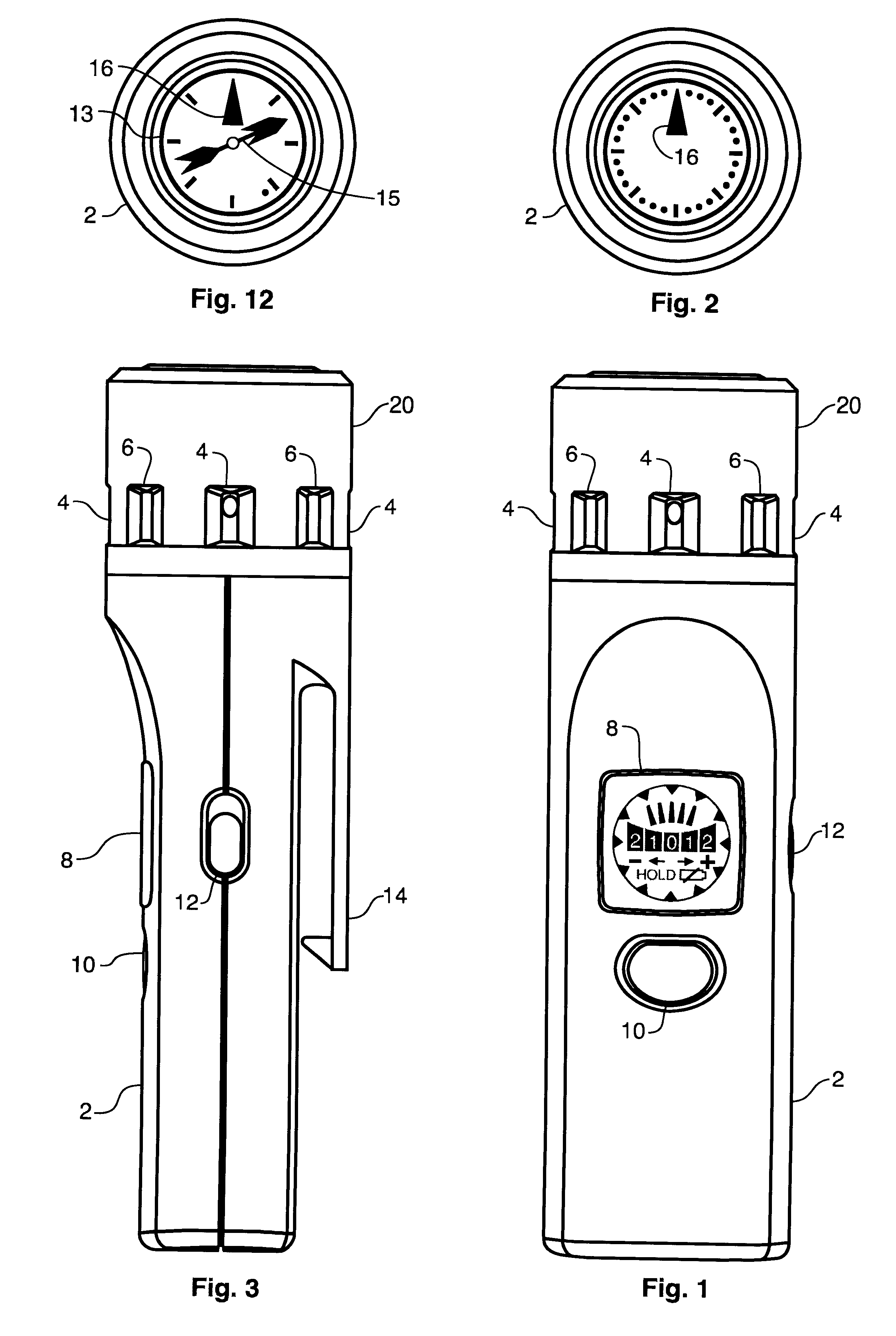
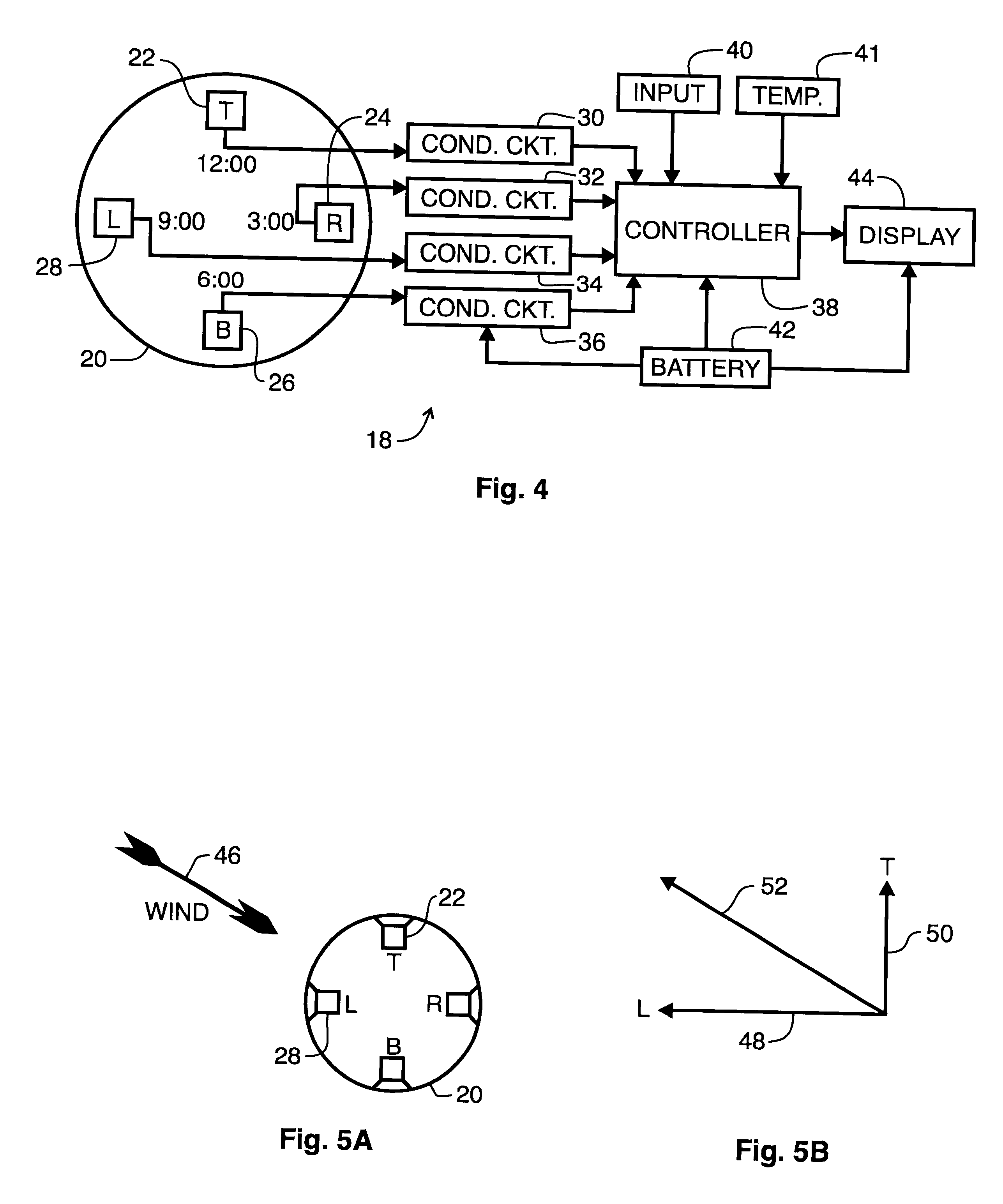
The present invention teaches a novel approach in the measurement of wind speed and direction. In an illustrative embodiment, condenser microphones are employed as sensor elements to detect wind pressure. Four sensor elements are positioned about a compass to enable the detection of relative wind direction in a hand held device. In the preferred embodiment, the ...


PUM

PropertyMeasurementUnit
corner frequencyaaaaaaaaaa
timeaaaaaaaaaa
speedaaaaaaaaaa

Abstract

A wind gauge apparatus and method. An illustrative embodiment includes a microphone positioned to engage wind pressure from a first relative direction and a controller coupled to receive an audio signal from the microphone. The controller compares the audio signal with plural threshold values, representative of wind pressure levels, and determines a first wind pressure level incident upon the microphone. Filtering and gain controls are used to condition the audio signal output from the microphone. Plural microphones are employed to allow that detection of wind direction and magnitude about a compass of directions. Digital signal processing is employed to process data. In an illustrative embodiment, the wind direction and magnitude data are used to recommend a golf club size adjustment and a golf swing direction adjustment to the user, who has taken a measurement of the wind with respect to a reference golf swing direction. In another embodiment, a temperature sensor is added and the controller calculates a wind chill factor.

Description

1. Field of the InventionThe present invention relates to wind speed and direction measurements. More specifically, the present invention relates to a portable device and method for measuring wind speed and relative direction as applied to golf club selection and golf swing determination.2. Description of the Related ArtThere are numerous uses for the measurement and indication of wind speed and direction. Traditional meteorological measurements have long included wind speed and direction. Many outdoor activities benefit from wind speed and direction measurements as well. Aviation, boating, construction, recreation, and sports activities all benefit from having current information about wind speed and direction.Meteorologists have long employed the rotary-cup anemometer and weather vane to measure wind speed and direction, respectively. These are both mechanical devices that are located above local terrain and structures, typically on an elevated pole, that react to air movement to ...

Claims


Application Information

Patent Timeline
Patent Type & Authority Patents(United States)
IPC IPC(8): A63B57/00A63B71/06G01P13/02G01P5/24G01P5/00
CPCA63B57/00A63B71/0622G01P5/24G01P13/02A63B2220/16A63B2220/30A63B2220/56A63B2220/76A63B2220/80A63B2220/808A63B2220/833
Inventor CLARK, JOHN M.CAMPBELL, IAN DWAYNECHOW, WATSON C. K.EDMONDSON, DAVID J.KO, MARCO C.LAM, ALAN M. L.LAM, VINCENT M. T.LEE, WAI-FONG
Owner GENERAL WIRELESS OPERATIONS
Learn More