
Dual piston drag damper for rotary-wing aircraft rotor

a technology of rotary-wing aircraft and dampers, which is applied in the direction of propellers, propulsive elements, water-acting propulsive elements, etc., can solve the problems of high vibration and stress levels in the fuselage, rare phenomena, and waste of weigh

Inactive Publication Date: 2004-01-13
EUROCOPTER
View PDF20 Cites 32 Cited by
  • Summary
  • Abstract
  • Description
  • Claims
  • Application Information

AI Technical Summary

Benefits of technology

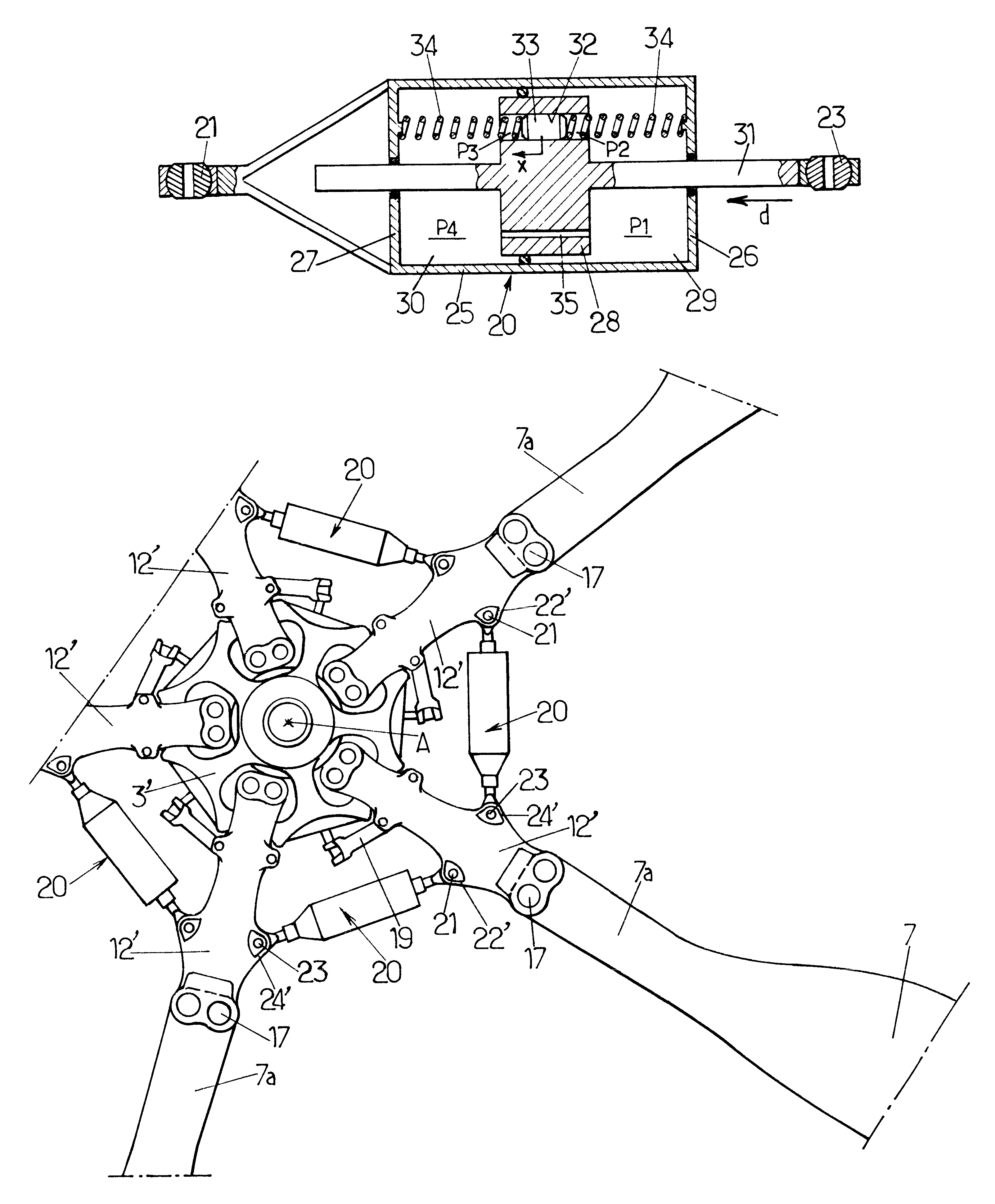
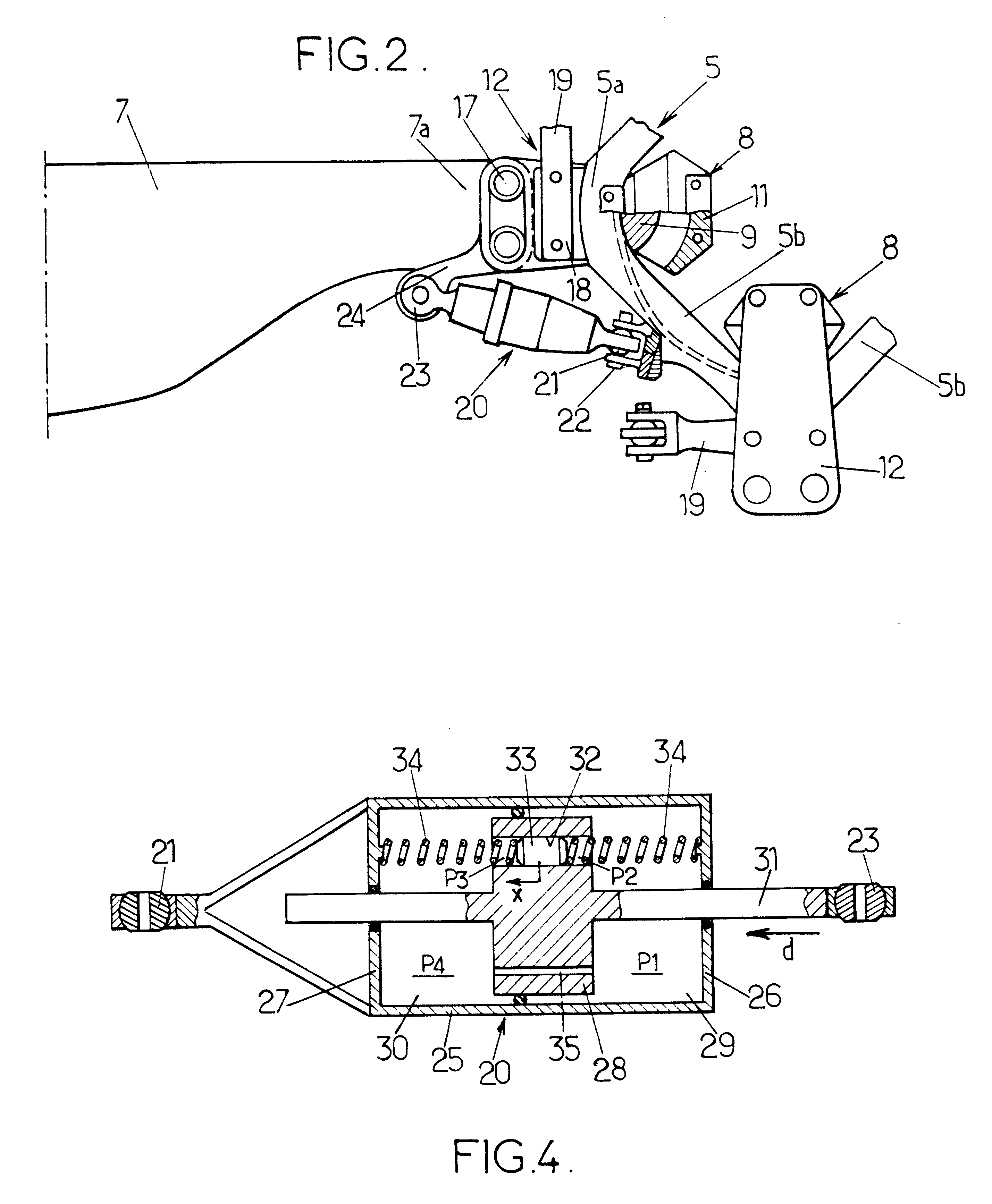
The drag damper according to the invention has the advantage of comprising at least two passages between the working chambers, one of which, with a larger cross-section that the other, houses a secondary piston, floating and subject to loading from the elastic bias, to filter or suppress the dynamic component at .OMEGA. in the stresses, by setting the resonance frequency of the secondary piston in the passage which receives it to the rotation frequency .OMEGA. of the rotor, while providing substantial damping for the natural drag mode of the blades at .omega..delta. by means of the other passage with a smaller cross-section, to counter the problems of air and ground resonance, without degrading the filtering of the .OMEGA. component.
In an advantageously simple embodiment, the channel may be made in the main piston and have longitudinal end portions which each open directly into one respectively of the working chambers.
In a simple manner, at least one restriction port may run substantially axially through the main piston, and the latter may be fitted to be slidable and pressure-tight in said body.

Problems solved by technology

From this there result alternating loads and moments on the rotor heads, and the development of high vibration and stress levels in fuselages.
However, it is known these phenomena rarely appear during the life of a helicopter.
Each drag damper therefore dissipates 97% of its energy on forced excitation at .OMEGA.. Under these conditions of use, this energy is dissipated to no purpose, which entails substantial fatigue in the components not only of the drag damper but of the means connecting it to the hub and to the flapping mass, and consequently wasted weight due to oversizing of these parts.
On the helicopter with a weight of about 8 to 10 t considered, the forces applied to the drag dampers upon forced excitation at .OMEGA. are very high, which may cause incidents in service such as cracks in the yokes connecting the drag dampers to the flapping masses, damage to the drag damper pins at the end where there are connected to the hub and also damage to the fittings connecting the drag dampers to the hub, and rapid deterioration of the ball joints used in these connection devices.
a forced response, at the nominal rotation frequency .OMEGA. of the rotor, which adversely affects reliability and the service life of the mechanical parts of the drag damper as well as of its devices connecting it to the hub and to the corresponding flapping mass or masses, and
In all cases, the dual-frequency stresses applied to drag dampers cause a substantial loss in the damping of the natural response, at the natural drag frequency of the flapping mass, which is a low frequency relative to the rotation frequency .OMEGA. of the rotor, this substantial loss of damping leading to the use of excess damping which adversely affects the reliability of the mechanical parts of the drag dampers as well as of their connections.

Method used


Image

  • Dual piston drag damper for rotary-wing aircraft rotor
  • Dual piston drag damper for rotary-wing aircraft rotor
  • Dual piston drag damper for rotary-wing aircraft rotor

Examples


Embodiment Construction

FIGS. 1 and 2 show schematically the head of a four-bladed helicopter main rotor substantially as described in EP 0 213 016 with reference to FIGS. 4 and 5 of that document, to which reference may advantageously be made for further details.

It will be recalled that this rotor head comprises a one-piece tubular mast-hub 1, the lower substantially cylindrical part of which forms a mast 2 with a base 4 designed to be connected in rotation to a main gearbox of the helicopter H (shown schematically in phantom outline) to drive the rotor in rotation about the axis A of the mast-hub 1. The latter also comprises an upper part forming a hub 3, which is an extension of the mast 2 and has the general external shape substantially of a truncated cone hollowed out at the end opposite to the mast 2 as far as a reinforcement ring 5 which constitutes the upper free end, thickened locally on its periphery, of the hub 3. Radial (relative to axis A) openings 6, identical and equal in number to the numbe...


PUM


Abstract

A drag damper for use on a rotary wing aircraft rotor comprises a body defining two variable volume chambers linked by a piston. The chambers are filled with fluid and are connected by a restriction port (35) and by a channel (32) of larger cross-section than the restriction port. A secondary piston slidable and pressure-tight piston is fitted in the channel and loaded by an elastic bias (34). The equivalent mass of this secondary piston (33) and of the fluid which it displaces, and the stiffness of the elastic bias (34) are such that the secondary piston is resonant in the channel (32) at the rotation frequency of the rotor, to filter the dynamic component at this frequency of stresses applied to the damper (20). Furthermore at the natural drag frequency of the corresponding blade, the elastic bias substantially blocks the secondary piston (33) in its channel (32), and the flow of fluid between the chambers (29, 30) of the damper (20) takes place mainly via the restriction port (35) calibrated to provide substantial damping at this frequency.

Description

The invention relates to a drag damper for a rotary-wing aircraft rotor comprising a hub and at least two blades each of which is connected to the hub by a corresponding connection device. The drag damper is intended for fitting between two elements, one of which is a flapping mass comprising one of the blades and the corresponding connection device, and the other element is one of the hub (in the conventional configuration) and an adjacent flapping mass on the rotor (in the so-called inter-blade configuration). In use, the drag damper will dampen the relative angular drag movements between said two elements, namely: in the first case (conventional configuration), the angular drag movements of said flapping mass relative to the hub, i.e. the angular deflections of the blade, and more generally of the corresponding flapping mass, about its drag axis, which is substantially parallel to the axis of rotation of the rotor; and in the second case (inter-blade configuration), the relative ...

Claims


Application Information

Patent Timeline
Patent Type & Authority Patents(United States)
IPC IPC(8): B64C27/32B64C27/00B64C27/35B64C27/51F16F9/20F16F9/50F16F9/14F16F9/504
CPCB64C27/35B64C27/51F16F9/20F16F9/504
Inventor ZOPPITELLI, ELIOLEGENDRE, PHILIPPE
Owner EUROCOPTER
Learn More