
Variable capacitor using MOS gated diode with multiple segments to limit DC current

a variable capacitor and diode technology, applied in the field of integrated circuit capacitors, can solve the problems of wasted area and variable capacitors that stop operating as desired

Inactive Publication Date: 2004-01-06
DIODES INC
View PDF17 Cites 20 Cited by
  • Summary
  • Abstract
  • Description
  • Claims
  • Application Information

AI Technical Summary

Benefits of technology

The present invention relates to an improvement in voltage-variable capacitors. The invention provides a way to adjust the capacitance of a MOS transistor or gated diode using a voltage gradient applied to the gate. This allows for a wider range of capacitances, rather than a limited quanta of capacitances selected by binary control signals. The invention also provides a way to control the capacitance using a MOS transistor in a voltage-controlled crystal oscillator circuit or a L-C tuning or tank circuit. The invention allows for more precise and accurate control of the capacitance, and provides greater flexibility in the design of integrated circuits.

Problems solved by technology

Since this turned-off region does not contribute to the capacitance, it is a wasted area.
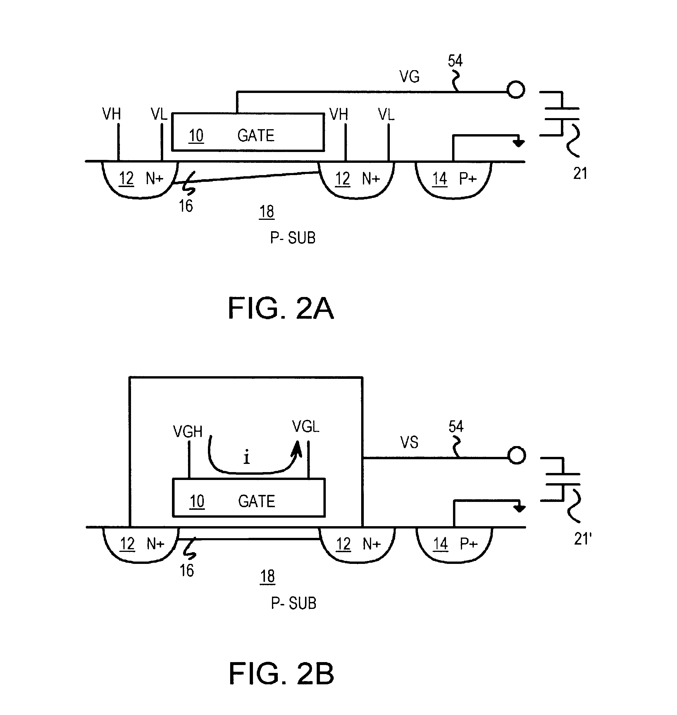
However, when the source voltage VS is above VGH, no channel is formed and the variable capacitor stops operating as desired.
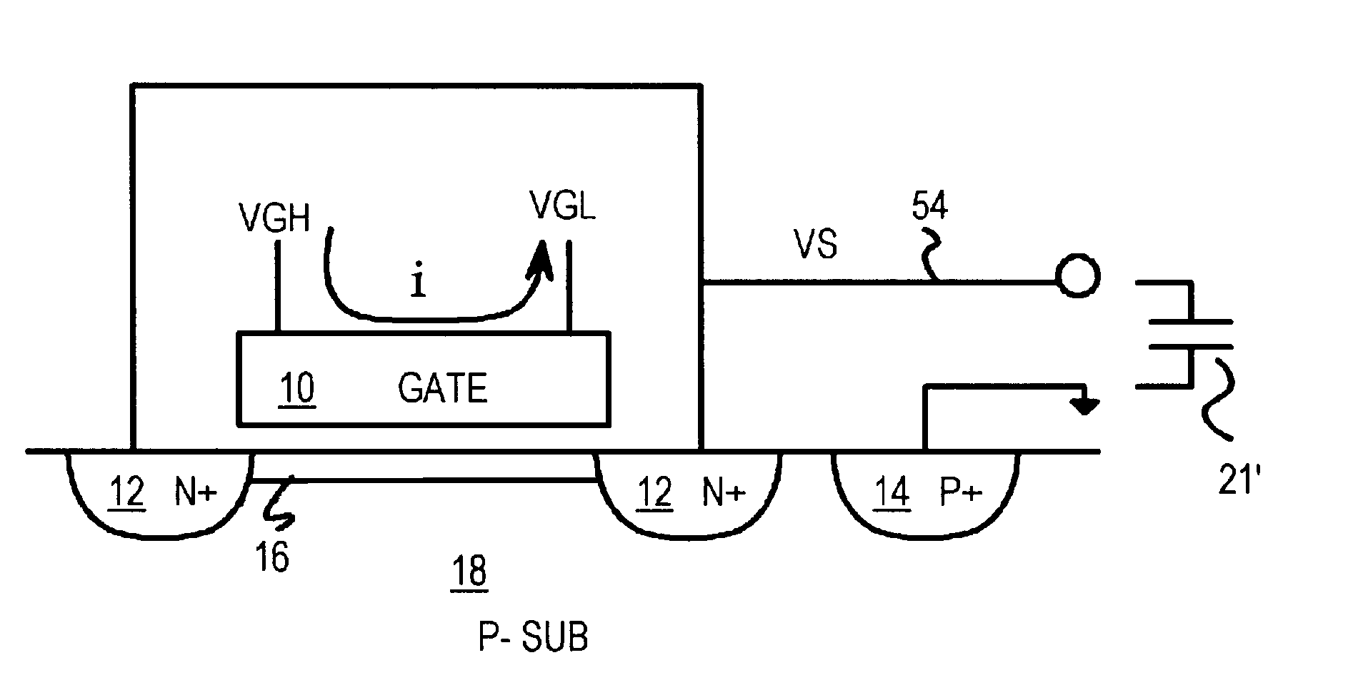
A disadvantage of the embodiments of FIGS. 3-5 is that current flows from upper contact 34 to lower contact 32 through the resistor of gate 30, For example, a 100-ohm gate resistance draws a current of 10 mA when VGH is 1 volt.

Method used


Image

  • Variable capacitor using MOS gated diode with multiple segments to limit DC current
  • Variable capacitor using MOS gated diode with multiple segments to limit DC current
  • Variable capacitor using MOS gated diode with multiple segments to limit DC current

Examples


Embodiment Construction

Several other embodiments are contemplated by the inventor. For example the substrate could be biased by a charge pump to a voltage other than ground. The external circuit uses the variable capacitor by connecting between line 54 and this substrate voltage. For example, the substrate could be biased to -3 volts, and the variable capacitor has a lower terminal at -3 volts. In an actual device layout, the source side can be used by itself without a drain side, or vice-versa. Using many metal contacts reduces resistance, but is not essential.

The terms source and drain are often used interchangeably, as a source / drain region can function as a source or a drain depending on the applied bias voltages. The source and drain regions do not have to have identical layouts or identical voltages. The drain can be biased to different voltages, although some current can flow from drain to source when the source and drain voltages are not equal. The variable capacitor could have only a source and n...


PUM


Abstract

A voltage-variable capacitor uses the channel-to-substrate junction from a gated diode formed from a metal-oxide-semiconductor transistor. The transistor gate has at least two contacts that are biased to different voltages. The gate acts as a resistor with current flowing from an upper gate contact to a lower gate contact. The gate-to-source voltage varies as a function of the position. A critical voltage is where the gate-to-source voltage is equal to the transistor threshold. A portion of the gate that has gate voltages above the critical voltage has an inversion layer or conducting channel under the gate. Another portion of the gate has gate voltages below the critical voltage, and thus no channel forms. By varying either the gate voltages or the source voltage, the area of the gate that has a channel under it is varied, varying the channel-to-substrate capacitance. Separate gate arms reduce bias current.

Description

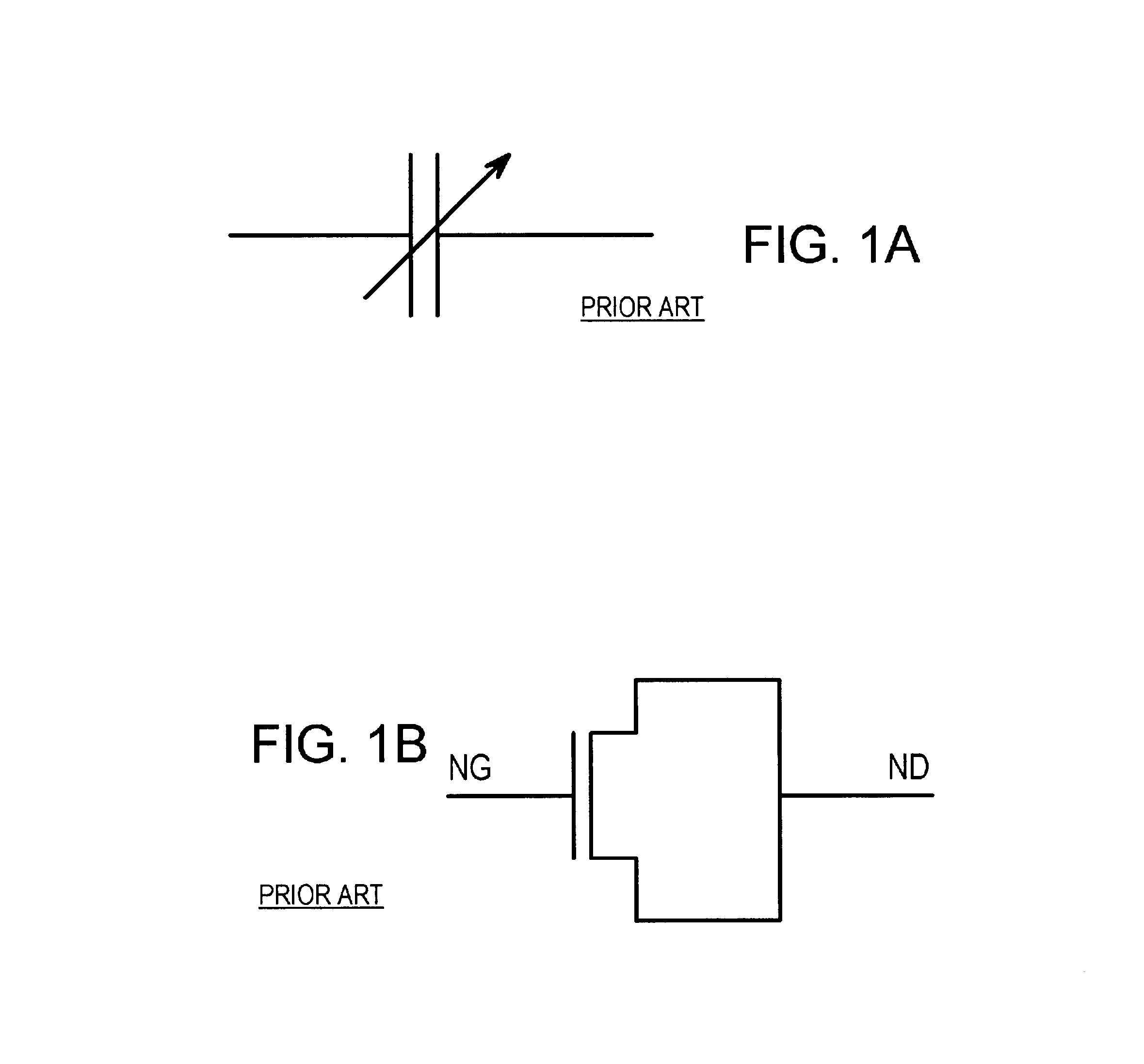
BACKGROUND OF INVENTIONThis invention relates to integrated circuit capacitors, and more particularly to voltage-variable integrated capacitors.Variable capacitors or varactors have been used for many years in tuning circuits. For example, radio receivers once used variable capacitors that adjusted a band-pass frequency in a tuning circuit, allowing one radio station to be amplified while suppressing other radio frequency signals. The amount of capacitance was varied by a user turning a dial that rotated half of the metal plates of the capacitor. As the user rotated the plates, the overlap area between adjacent metal plates varied, thus varying the capacitance value. FIG. 1A shows a symbol for a variable capacitor or varactor.More recently, capacitors have been integrated onto larger integrated circuit (IC) chips. Often a capacitor is formed from a metal-oxide-semiconductor (MOS) field-effect transistor. FIG. 1B shows a prior-art MOS capacitor. The source and drain terminals of the ...

Claims


Application Information

Patent Timeline
Patent Type & Authority Patents(United States)
IPC IPC(8): H01L29/66H01L29/94
CPCH01L29/94
Inventor CAO, MIN
Owner DIODES INC
Learn More