Electronic device

a technology of electronic devices and lcds, applied in non-linear optics, instruments, optics, etc., can solve the problems of inconvenient use, increased manufacturing costs, and inability to meet the needs of users, so as to improve the quality of information, increase manufacturing costs, and influence the amount and/or quality of information

Inactive Publication Date: 2003-12-23
TELEFON AB LM ERICSSON (PUBL)
View PDF7 Cites 2 Cited by
  • Summary
  • Abstract
  • Description
  • Claims
  • Application Information

AI Technical Summary

Benefits of technology

It is an object of the invention to provide an electronic device as mentioned in the opening paragraph in which the areas of the LCD that are hidden or shaded when seen under normal viewing angles as described above are reduced. This object should be achieved without enlarging the LCD which would increase the manufacturing costs, and furthermore a larger LCD would undesirably take up more space in the electronic device. The object should also be achieved without decreasing the active area of the LCD since this would influence the amount and / or quality of information shown by the LCD.
In a second embodiment of the invention, the masking is made of a foil material positioned between the LCD and the front light guiding plate. In this embodiment one more structural part is included than those included in the prior art devices. An advantage is, however, that the masking may be changed by exchanging the foil only and, furthermore, the foil material can be used for providing the necessary gap between the LCD and the front light guiding plate.
Preferably all edges of the opening in the front are positioned above areas covered by the masking between the LCD and the front light guiding plate. This means that all edges of the front are retracted in relation to the edges of the masking, thereby minimizing the occurrences of hidden or shaded areas at any edges of the LCD.

Problems solved by technology

This object should be achieved without enlarging the LCD which would increase the manufacturing costs, and furthermore a larger LCD would undesirably take up more space in the electronic device.
Furthermore, a light source, e.g. the sun, will only cast a shadow over the theoretical viewing area if the light falls on the LCD at a very acute angle.

Method used


Image

  • Electronic device
  • Electronic device

Examples


Embodiment Construction

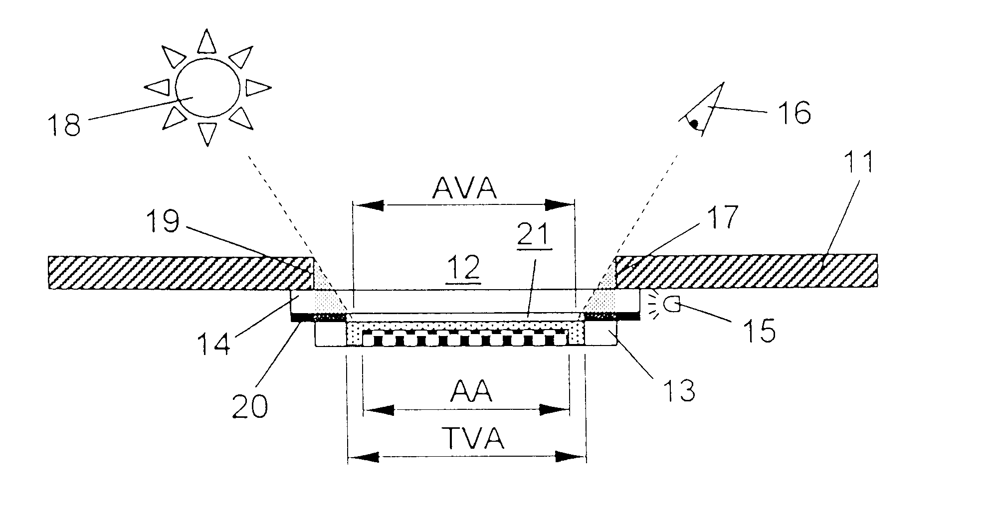
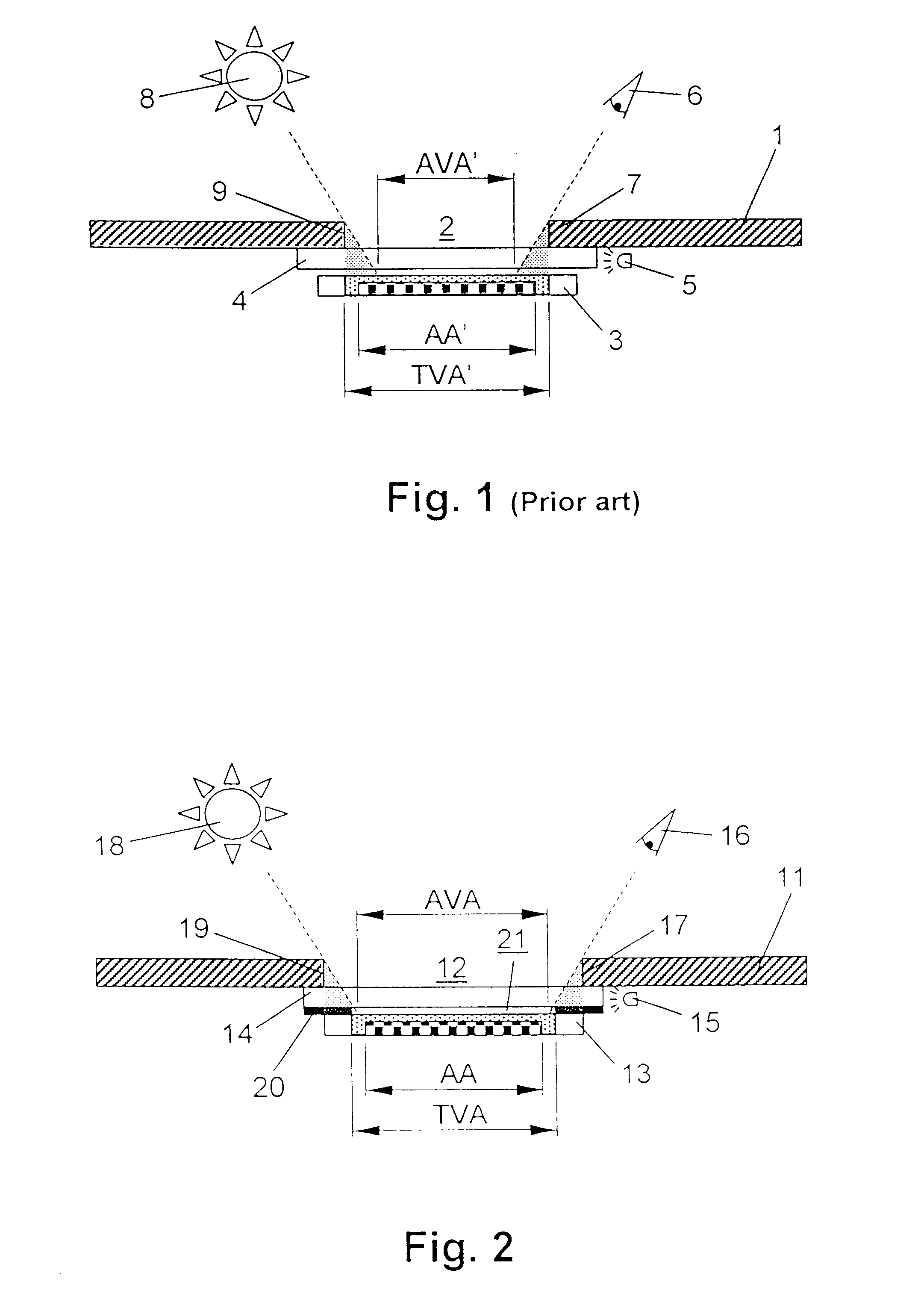
FIG. 1 shows a portion of an electronic device provided with an LCD according to the prior art. The electronic device comprises a front 1 having an opening 2 through which an LCD 3 can be seen. A transparent front light guiding plate 4 is positioned between the front 1 and the LCD 3, and a light source 5 is arranged at one edge of the front light guiding plate 4.

The LCD 3 has a theoretical viewing area TVA' corresponding to the area that can be seen through the opening 2 in the front 1 when viewed in a direction that is perpendicular to the front 1. In the theoretical viewing area TVA' the appearance of the LCD 3 fulfils high cosmetic requirements since this area is the area that the user can see. The areas outside the theoretical viewing area TVA' can normally not be seen by the user.

The LCD 3 also has an active area AA' that is the area in which pixels can be activated / deactivated, i.e. the area showing the desired information. The active area AA' is generally smaller than the the...


PUM

PropertyMeasurementUnit
distanceaaaaaaaaaa
transparentaaaaaaaaaa
areasaaaaaaaaaa

Abstract

An electronic device provided with a front lit LCD (13) having a theoretical viewing area (TVA). The electronic device comprises a transparent front light guiding plate (14) extending between the LCD (13) and a front (11) of said electronic device and the front (11) has an opening (12) through which the LCD (13) can be viewed through the transparent front light guiding plate (14). A masking (20) is provided between the LCD (13) and the front light guiding plate (14), said masking (20) having an opening (21) that substantially corresponds to the theoretical viewing area (TVA) of the LCD (13), and extending outwards from said opening (21). The opening (12) in the front (11) of the electronic device is larger than the opening (21) in the masking (20).

Description

The invention relates to an electronic device provided with a front lit LCD having a theoretical viewing area, said electronic device comprising a transparent front light guiding plate extending between the LCD and a front of said electronic device, said front having an opening through which the LCD can be viewed through the transparent front light guiding plate.RELATED PRIOR ARTAn electronic device of this kind is known from GB-A-2 336 933 that shows the structure of a front lighting means for a liquid crystal display (LCD) for use in an electronic device. The electronic device comprises an upper casing provided with a front opening through which an LCD can be seen. A light guide member is positioned between the front opening and the LCD, said light guide member consisting of a transparent plate made of e.g. acrylic resin. A light source is provided near the edge of the light guide member and reflectors lead the light emitted from the light source to the edge of the light guide mem...

Claims


Application Information

Patent Timeline
Patent Type & Authority Patents(United States)
IPC IPC(8): G02F1/13G02F1/1335G02F1/13357
CPCG02F1/1336G02F1/133509G02F1/133512G02F2001/133626G02F2001/133616G02F1/133616G02F1/133626
Inventor EK, MARTINSCHACK, GORAN
Owner TELEFON AB LM ERICSSON (PUBL)
Why Eureka
Try Eureka