
Liquid crystal driver circuit and LCD having fast data write capability

a driver circuit and liquid crystal technology, applied in the direction of instruments, static indicating devices, etc., can solve the problems of reducing picture quality, difficult for the conventional driver circuit to write data into the high-load liquid crystal panel, and incompatibility with high-resolution methods, etc., to achieve rapid writing, reduce charge time, and increase the resolution and size of the liquid crystal panel

Inactive Publication Date: 2003-12-09
PANASONIC LIQUID CRYSTAL DISPLAY CO LTD +1
View PDF7 Cites 46 Cited by
  • Summary
  • Abstract
  • Description
  • Claims
  • Application Information

AI Technical Summary

Benefits of technology

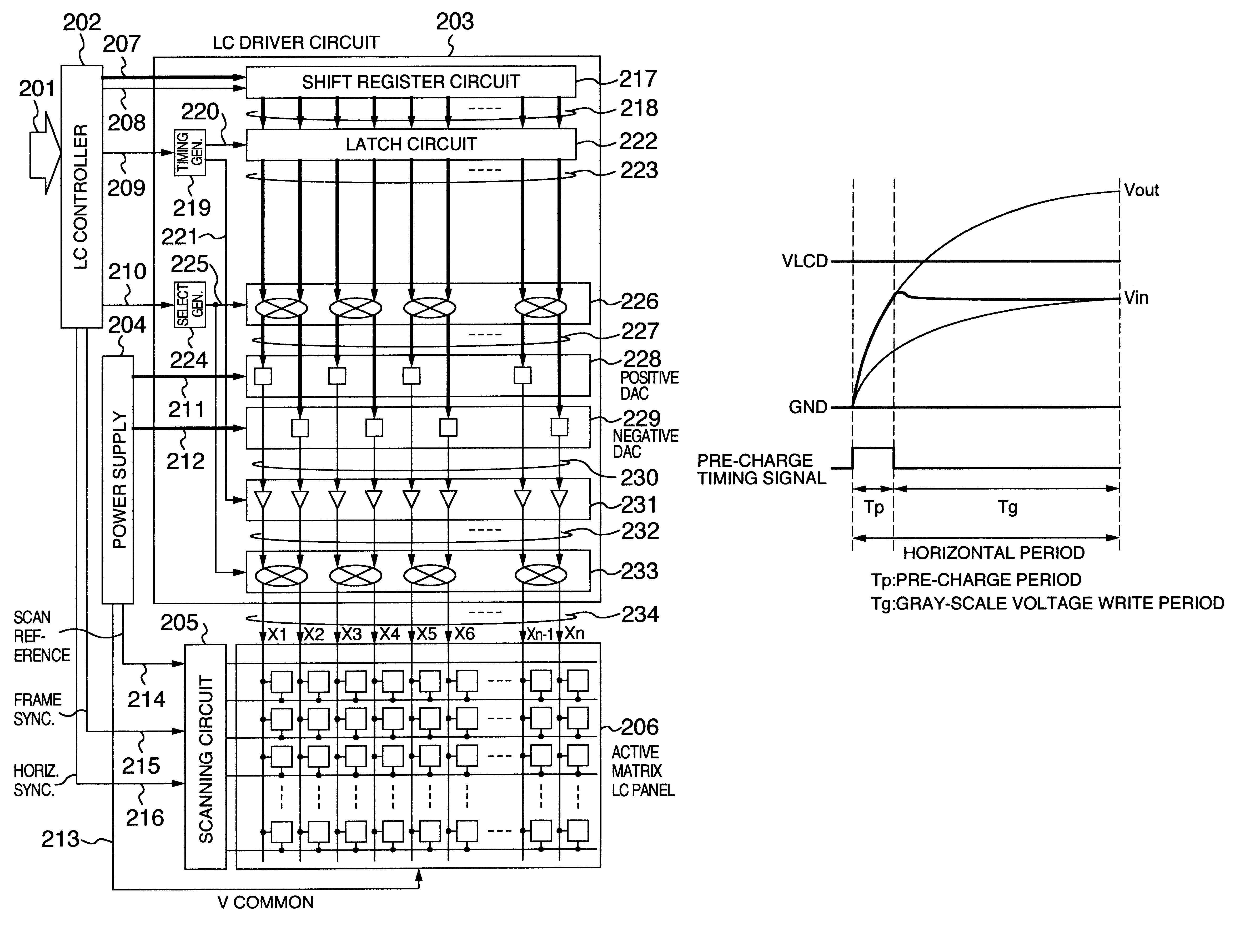
The horizontal period, which is the liquid crystal panel write time, is about 14 .mu.s for the resolution of XGA and about 11 .mu.s for SXGA. The horizontal period is reduced as the resolution increases, that is, about 9.mu.s for UXGA, about 7 .mu.s for QXGA, and about 5 .mu.s for QSXGA. The liquid crystal panel load also increases as the panel size increases; that is, the load of a 18-inch panel is about 1.2 times higher, and the load of a 20-inch panel is about 1.33 times higher, than that of a 15-inch panel.
It is an object of the present invention to provide a liquid crystal driver circuit and an LCD which quickly write data into a liquid crystal panel with a large load capacity and load resistance to display high quality pictures on a high-resolution, large-sized liquid crystal display.

Problems solved by technology

In response to an increase in the resolution and size of a liquid crystal panel, the conventional driving method is designed for reducing the charge time (horizontal period) and the liquid crystal panel load but not for quickly writing data on the liquid crystal panel.
That is, the conventional method is not compatible with a high-resolution, large-sized liquid crystal panel.
Therefore, it is difficult for the conventional driver circuit to write data into a high-load liquid crystal panel in such a short charge time.
The picture quality is degraded because of an insufficient write voltage.

Method used


Image

  • Liquid crystal driver circuit and LCD having fast data write capability
  • Liquid crystal driver circuit and LCD having fast data write capability
  • Liquid crystal driver circuit and LCD having fast data write capability

Examples


Embodiment Construction

An embodiment of a dot inversion drive method of a liquid crystal display will be described with reference to FIGS. 1, 2, 9, and 10.

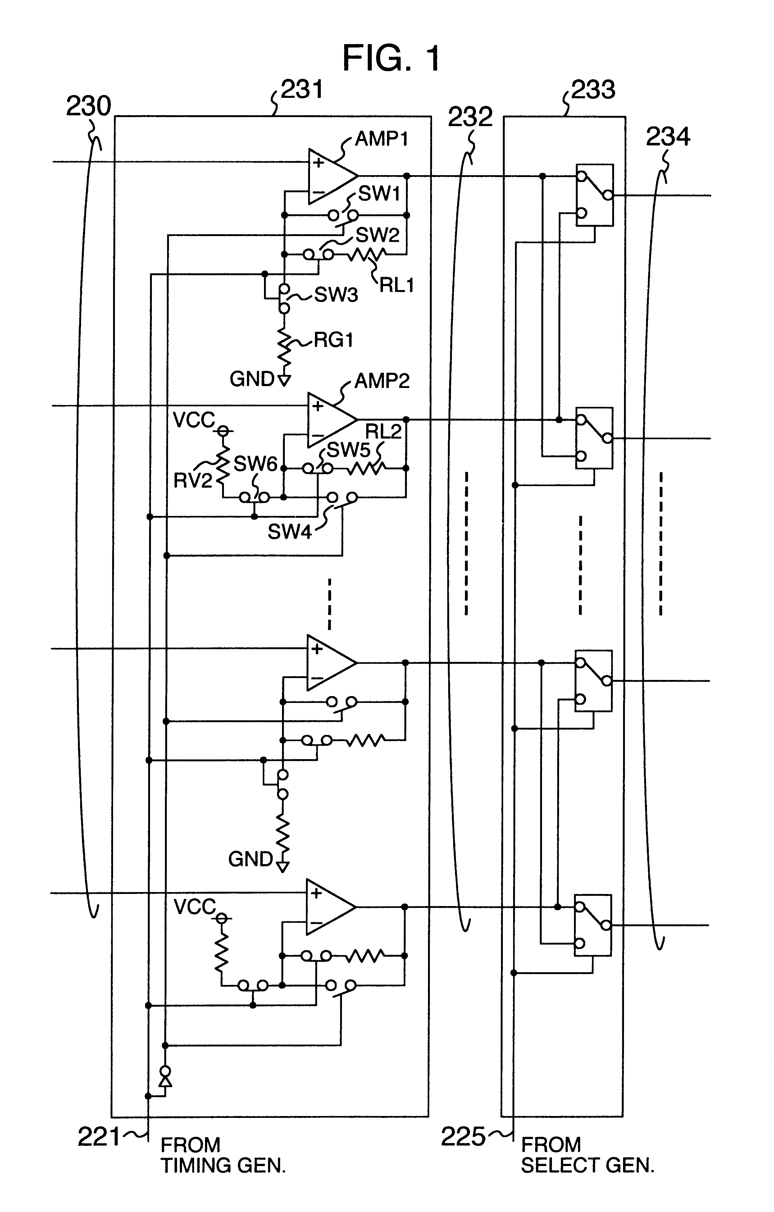
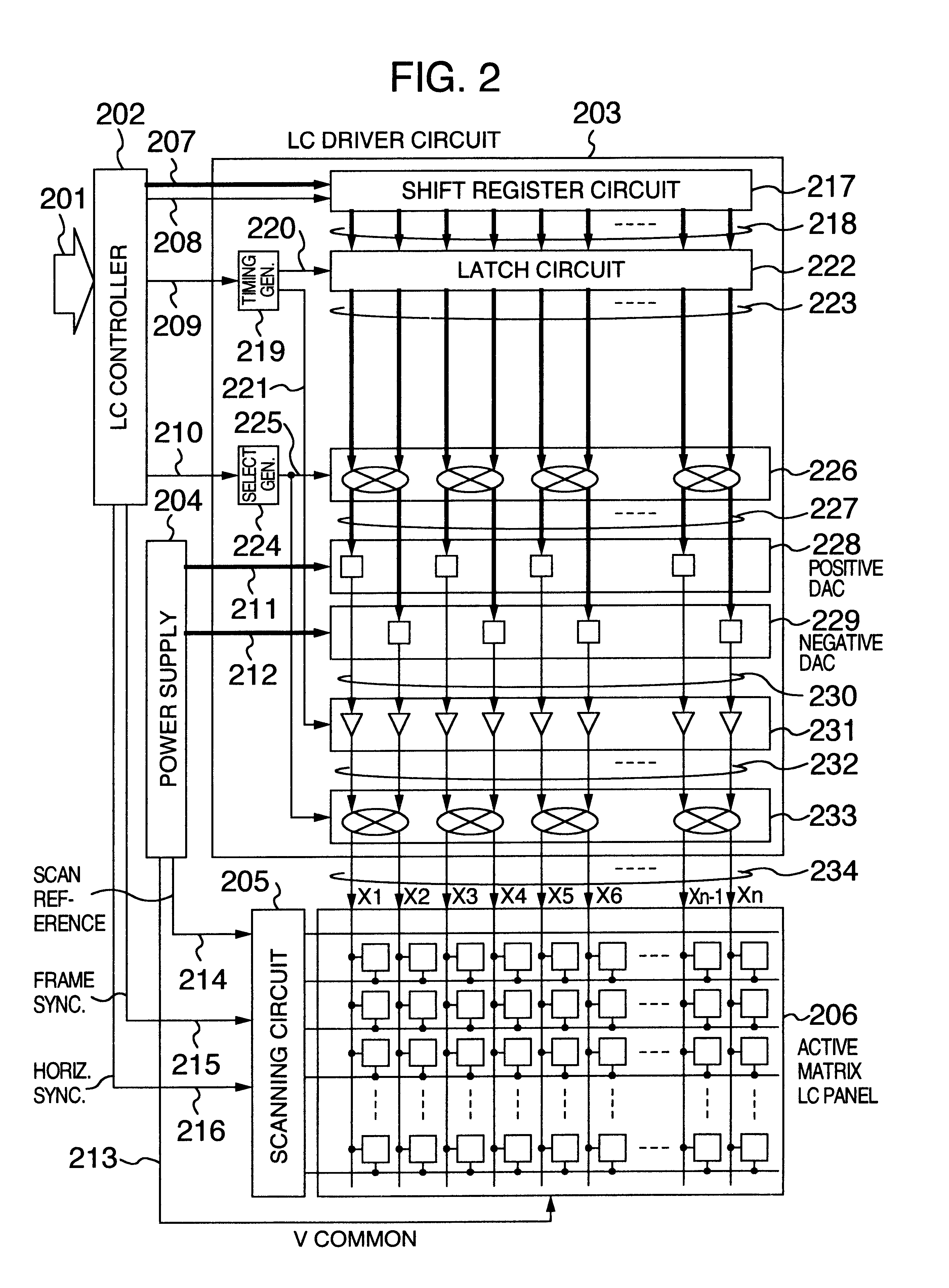
FIG. 1 shows a configuration of an output circuit within a liquid crystal driver circuit, and FIG. 2 shows a configuration of the liquid crystal driver circuit. In the Figures, numeral 201 indicates a display signal set transferred from a system unit, numeral 202 indicates a liquid crystal controller which converts the display signal set 201 to the synchronizing signal and display data of a liquid crystal driver circuit, numeral 203 indicates la liquid crystal driver circuit which applies a driving voltage corresponding to the display data to the liquid crystal panel, numeral 204 indicates a power supply circuit which generates a gray-scale voltage and reference voltage of the liquid crystal panel, numeral 205 indicates a scanning circuit which performs line-sequential selection for the liquid crystal panel, and numeral 206 indicates an active matrix li...


PUM


Abstract

A fast-write, high picture-quality LCD (Liquid Crystal Display) compatible with a high-resolution, large-sized liquid crystal panel. An output amplifier circuit of a liquid crystal driver circuit includes an amplifier configuration, which functions as an amplifier that amplifies the predetermined gray-scale voltage for output and as an amplifier that buffers the predetermined gray-scale voltage and outputs with no amplification, and a circuit for switching the above two types of amplifiers. In each horizontal period, a liquid crystal panel is driven by the amplified output for a predetermined period and by the buffered output for the rest of the period. A pre-charge control circuit is provided to check whether the gray-scale voltage is to be amplified depending upon display data.

Description

BACKGROUND OF THE INVENTIONThe present invention relates to a liquid crystal driver circuit which displays data on a liquid crystal display, and more particularly to a liquid crystal driver circuit which applies a drive voltage to a liquid crystal panel at a high speed.As described in "An 8-bit Digital Data Driver for Color TFT-LCDs", pp. 247-250, in SID DIGEST, 1996, the data driver circuit (liquid crystal driver) of a conventional liquid crystal display (LCD) buffers a liquid crystal application voltage corresponding to display data generated by a digital-to-analog converter (DAC) circuit with the use-of an output amplifier circuit before output. The output amplifier circuit, composed of a voltage follower circuit, applies a gray-scale voltage of the DAC circuit directly to the liquid crystal panel pixels to display data.SUMMARY OF THE INVENTIONIn response to an increase in the resolution and size of a liquid crystal panel, the conventional driving method is designed for reducing ...

Claims


Application Information

Patent Timeline
IPC IPC(8): G09G3/36G02F1/133G09G3/20
CPCG09G3/2011G09G3/3688G09G3/3614G09G2310/0291G09G2310/0248G09G2310/027G09G3/36
Inventor NITTA, HIROYUKIKAWABE, KAZUYOSHITSUNEKAWA, SATORUKOSHI, HIROBUMI
Owner PANASONIC LIQUID CRYSTAL DISPLAY CO LTD
Learn More