Apparatus and compensation method for ports variation

a compensation method and port technology, applied in the direction of oscillator generators, pulse automatic control, electrical apparatus, etc., can solve the problems of large distortion of operation, inability to design circuits as narrow as could ideally be wished, and inability to achieve the effect of reducing the distortion of operation

Inactive Publication Date: 2003-11-04
MACOM TECH SOLUTIONS HLDG INC
View PDF4 Cites 0 Cited by
  • Summary
  • Abstract
  • Description
  • Claims
  • Application Information

AI Technical Summary

Problems solved by technology

Due to inherent inconsistencies in manufacturing procedures or raw material qualities, the initial frequency obtained may vary, thus the range of voltage cannot be as narrow as could ideally

Method used


Image

  • Apparatus and compensation method for ports variation
  • Apparatus and compensation method for ports variation
  • Apparatus and compensation method for ports variation

Examples


Embodiment Construction

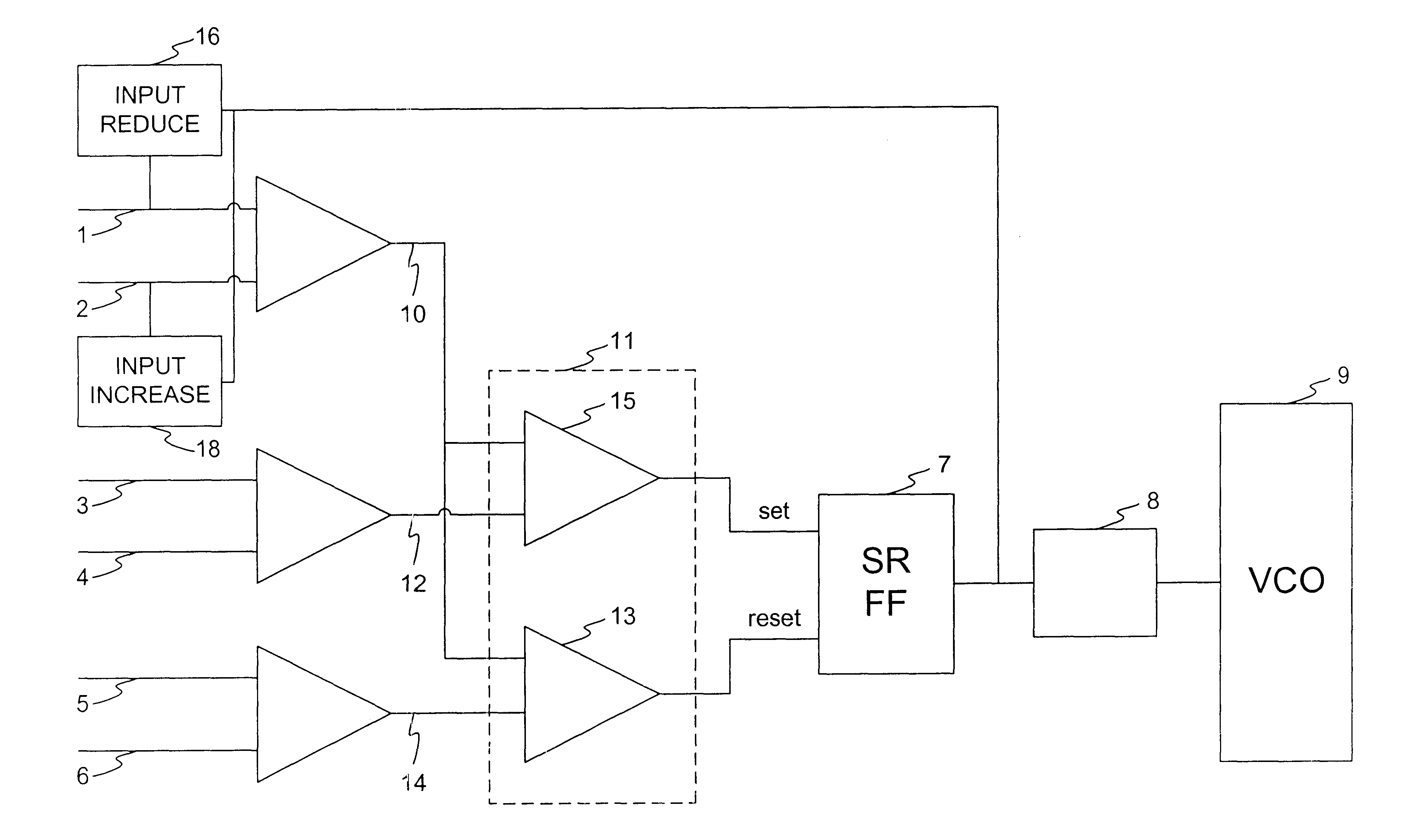
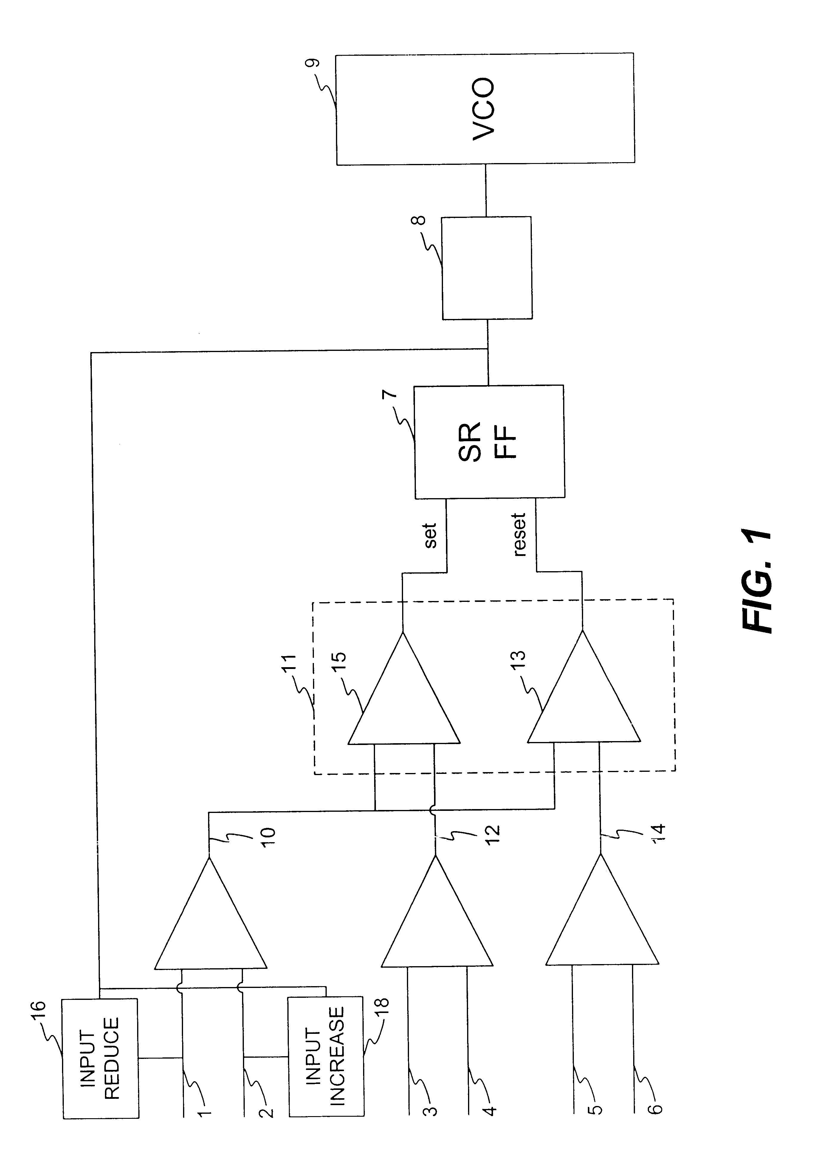
An exemplary embodiment of the present invention is shown for use in combination with a differential VCO.

A circuit for monitoring and controlling input to a VCO, generally comprises (a) a monitoring sub-circuit for monitoring input; (b) a stepping sub-circuit for stepping the VCO's frequency range; (c) an input reduction sub-circuit for reducing input into said monitoring sub-circuit; and (d) a VCO.

Referring to FIG. 1, differential voltage 10 comprising input voltage 1 and input voltage 2 is compared to reference voltage 12 comprising input 3 and input 4. Comparator 11, comprised of differential amplifiers 13 and 15, compares differential voltage 10 and reference voltage 12, which are input to the amplifiers 13 and 15, and is responsible for setting set / reset flip-flop (SR-FF) 7 when the comparison is equal, i.e. differential voltage 10 has reached the upper limit specified by reference voltage 12.

When SR-FF 7 is set:

[1] Counter 8 is incremented,

[2] VCO 9 is calibrated, i.e. stepped...


PUM


Abstract

A circuit for monitoring and controlling input to a VCO, comprises: (A) a monitoring sub-circuit for monitoring input; (B) a stepping sub-circuit for stepping the VCO's frequency range; (C) an input reduction sub-circuit for reducing input into the monitoring sub-circuit; and (D) a VCO.

Description

This invention relates to phase lock loops (PLLs). More specifically, this invention relates to monitoring and controlling the input voltages to the "voltage controlled oscillator" (VCO) for use in optimizing a PLL.A PLL (Phase Lock Loop) is a basic design in communication chips. The PLL's design goal is the generation of a clock with precise frequency and phase by control over a "VCO" block (Voltage Controlled Oscillator) that is part of the PLL.The smaller the "VCO gain" (the ratio of additional voltage vs. additional frequency) is, the better is the precision of the control over the VCO and frequency. Additionally, reduced VCO gain improves resistance to noise as well, because a small range of frequency is relating to a wide range of voltage (i.e. a major change in the input voltage will produce only a minor adjustment in the frequency).In order to utilize narrow bands of voltage level in the circuit (i.e. a reasonable range of 10 millivolts-1 volt), the design should be one wher...

Claims


Application Information

Patent Timeline
IPC IPC(8): H03L7/099H03L7/08H03L7/10
CPCH03L7/10H03L7/099
Inventor COHEN, AVRAHAMSCHWARTSGLASS, OFFER
Owner MACOM TECH SOLUTIONS HLDG INC
Why Eureka
Try Eureka